Getting Started in Cisco Packet Tracer - 2023
Summary
TLDRThis video tutorial offers an introduction to Cisco Packet Tracer, a network simulation tool. It walks viewers through the software's interface, highlighting the toolbar categories for network devices, end devices, and connections. The guide demonstrates creating a logical network topology with routers, switches, and end devices, then transitions to the physical view for a realistic setup. It also covers cable management, device inspection, and power management, encouraging practice and exploration for various network configurations.
Takeaways
- π Cisco Packet Tracer offers a variety of features for network simulation, including different network devices and components.
- π The bottom toolbar in Packet Tracer is organized into categories like network devices, end devices, and connections for easy navigation.
- π¦ Network device category includes subcategories such as routers, switches, hubs, wireless devices, and more for building network topologies.
- π’ End devices category covers a range of devices from hosts to IoT-enabled smart devices and industrial equipment.
- π WAN emulation is available for simulating wide area networks within the Packet Tracer environment.
- π Connections category provides options for cabling, including structured cabling with physical view items like patch panels and connectors.
- π§ The miscellaneous category includes custom-made devices with pre-installed components for unique network configurations.
- π₯ Multi-user connection allows for collaboration on network designs across local or wide area networks.
- π Logical View mode in Packet Tracer is used to build the initial network topology before transitioning to the physical layout.
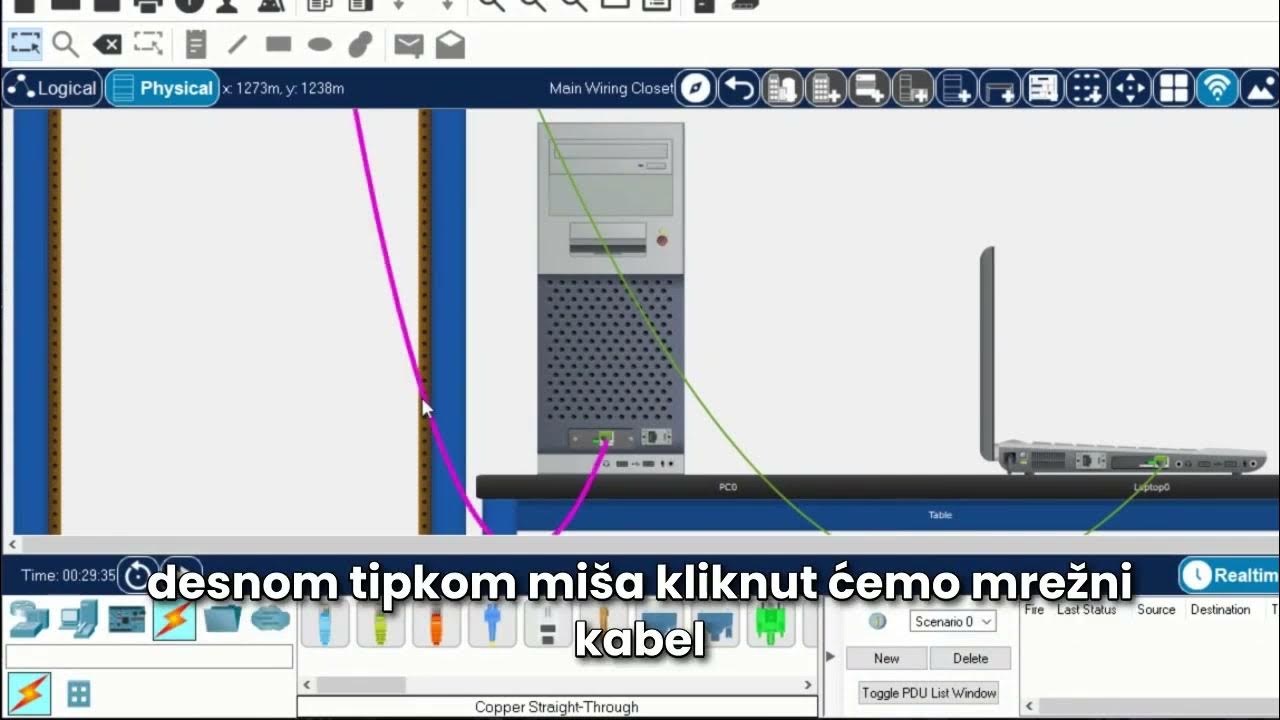
- π¬ Physical View mode provides a detailed, realistic representation of network devices and cabling for better visualization and management.
- π οΈ Management tools in Physical View, such as 'manage cable' and 'inspect', help in organizing and identifying network connections efficiently.
Q & A
What is the purpose of the Cisco Packet Tracer walkthrough video?
-The purpose of the Cisco Packet Tracer walkthrough video is to demonstrate the different features built inside the program and to guide users on how to use the Cisco Packet Tracer application.
What are the main categories found in the bottom toolbar of Cisco Packet Tracer?
-The main categories in the bottom toolbar of Cisco Packet Tracer include Network Devices, End Devices, Components, Connections, Miscellaneous, and Multi-User Connection.
What types of devices can be found under the Network Devices category?
-Under the Network Devices category, you can find devices like routers, switches, hubs, wireless devices, security devices, and WAN emulation devices.
What is the default subcategory under the Network Devices category?
-The default subcategory under the Network Devices category is routers.
What are the different types of devices that can be found under the End Devices category?
-Under the End Devices category, you can find hosts, smart network-enabled IoT devices, city-wide devices, industrial devices, and power grid devices.
What is the purpose of the Components category in Cisco Packet Tracer?
-The Components category in Cisco Packet Tracer is used for deploying various different boards, actuators, and sensors in a network.
How does the Connections category help in building a network topology?
-The Connections category provides common types of cabling and structured cabling options that are used to interconnect devices in a network topology.
What is the difference between the Logical View and Physical View in Cisco Packet Tracer?
-The Logical View in Cisco Packet Tracer is used to build a logical topology, while the Physical View allows users to build a network and interconnect devices in a more realistic, physical environment.
How can you manage cabling in the Physical View of Cisco Packet Tracer?
-In the Physical View, you can manage cabling by right-clicking on a network cable and choosing options like delete, color the cable, or manage cable to organize the cables neatly.
What are some actions you can perform on a device in Cisco Packet Tracer?
-In Cisco Packet Tracer, you can perform actions such as inspecting the front or rear of a device, deleting the device, unmanaging cables on the device, or managing all cables on the device.
How can you add a server to the network topology in Cisco Packet Tracer?
-To add a server to the network topology in Cisco Packet Tracer, select the server from the End Devices category, click on the network rack, and then connect it using a straight through cable from the server's network interface card to a port on the switch.
Outlines
π Introduction to Cisco Packet Tracer Features
This paragraph introduces the video's focus on demonstrating the features of Cisco Packet Tracer. It begins with an overview of the toolbar at the bottom left, highlighting the categories and subcategories available for network device selection, such as routers, switches, and hubs. The script then moves on to discuss other device categories like end devices, smart city devices, and IoT components. The paragraph concludes with an introduction to the connections category, which includes cabling options for network setup, and touches on the multi-user connection feature for network collaboration.
π Building a Logical Network Topology
The second paragraph delves into the process of creating a logical network topology using Cisco Packet Tracer. It describes selecting devices from the network devices category, such as routers and switches, and placing them into the logical topology. The script also covers adding end devices like PCs and laptops, and using the connections category to interconnect these devices with the appropriate cabling. The paragraph explains the visual indicators for port status and connectivity, and it transitions into discussing the physical view of network construction.
π Exploring Physical Network Topology and Device Management
This paragraph discusses the transition from logical to physical view in Cisco Packet Tracer, detailing the process of arranging and organizing network devices in a physical environment. It covers the use of the physical tab to change the view, the ability to scroll and zoom for better visualization, and the management of cabling to maintain a tidy workspace. The script explains how to use the manage cable feature for devices on a network rack and the options available for inspecting the front and rear of devices like switches and routers. It also touches on the process of deploying new devices onto the existing physical topology and the steps for connecting them using the provided cabling.
Mindmap
Keywords
π‘Cisco Packet Tracer
π‘Network Devices
π‘Logical View
π‘Physical View
π‘Topology
π‘End Devices
π‘Connections
π‘Cabling Management
π‘Multi-User Connection
π‘IoT (Internet of Things)
π‘Smart City
Highlights
Introduction to Cisco Packet Tracer and its features.
Exploring the bottom toolbar and its categories for different network components.
Default category is Network Devices with options like routers and switches.
Hubs, wireless devices, and security devices are also available categories.
WAN emulation for wide area network configurations.
End devices category includes hosts, IoT devices, and smart city devices.
Components category for different boards, actuators, and sensors in IoT.
Connections category for cabling and structured cabling options.
Physical view features like patch panels, connectors, and wall mounts.
Miscellaneous category for custom-made devices and components.
Multi-user connection for interconnecting Packet Tracer instances over networks.
Building a logical topology in Logical View mode.
Deploying routers, switches, PCs, and laptops in the logical topology.
Interconnecting devices using cabling from the connections category.
Switching to Physical View for a more realistic network setup.
Organizing devices and cabling on the network rack in Physical View.
Managing cables with options to delete, color, or tidy up connections.
Inspecting front and rear views of devices for detailed configuration.
Power management for devices like routers and switches.
Adding new devices like servers to the physical topology.
Utilizing logical and physical views for comprehensive network configurations.
Transcripts
hello everyone Welcome to our getting
started and Cisco Packet Tracer
walkthrough video in this video I can
just show you the different features
built inside of the program known as
Cisco Packet Tracer as we get started
we'll highlight some of the key
components of using the Cisco Packet
Tracer application let's begin by taking
a look at the bottom toolbar and I'm
looking the bottom left corner
here we have a variety of different
categories and in each category we're
going to have options below for example
the default category is network devices
that's selected by default
and the network device category will
find the subcategory of routers with
router selected we'll see a variety of
different model routers available for us
to put into our topology
if I click on the next item it's
switches inside of our Network device
category and then my list will now
contain Network switches that I can
deploy inside of my topology above
the next category is hubs file the
course by wireless devices
including then the next category of
security
and then finale is and then finally is
wan emulation for a wide area Networks
outside of the network device category
we can find the next main category of
end devices
if I click on end devices our default
subcategory is an end devices of
different types of hosts and other
equipment we can put on our Network
there's another subcategory for end
devices which is home and this brings in
a lot of our smart Network enabled iot
devices
we can go further by looking at
city-wide devices which are under the
category of smart City within end
devices
if we continue on the next component
will be Industrial and then even power
grid all bringing some great features
into Cisco package razor and the type of
devices we can deploy in a network
to go even further into the realm of
Internet of Things known as iot we have
another main category known as
components
and in components you'll find a variety
of different boards
also we have another subcategory for
actuators and even sensors
these can be deployed in a network just
like what we're doing now
to interconnect your devices we'll be
utilizing the connections category
in the connections category we have two
subcategories we have connections which
is our common type of cabling we'll be
using
but also another subcategory is
structured cabling and here you will
find items that are available in
physical view of Cisco Packet Tracer and
these will include patch panel
connectors and wall mounts
the next category is miscellaneous and
here we will find some custom-made
devices with components already
installed
lastly the category of multi-user
connection allows us to interconnect our
package razor instance with others
across a local area network or even a
wide area network connection
let's continue by creating a small
Network utilizing our Cisco Packet
Tracer logical View
by default we can see our Packet Tracer
has opened in The Logical View mode this
is where we can build a logical topology
I'm going to select the main category in
the bottom toolbar of network devices
the default selection again is routers
and I'll go ahead and take a look at the
routers available
at this time I may want something like a
four three three one Cisco router I can
click on that and then I can click in
our logical topology
I can continue by deploying now a
network switch
I will click on the subcategory for
switches and I'll click the first switch
available
I will then click on my logical topology
and now it is ready
at this time I'd like to add on two or
three end devices so I'll click on the
category of end devices
the default subcategory of our end
devices is already selected and I will
go ahead and take one PC and click it on
put it right in the logical topology
and one laptop I will click and click on
the logical topology
at this time I'd like to interconnect
these by utilizing our cabling that is
under our connections category
I will click on connections the default
subcategory of connections is already
selected and I will choose the
appropriate cabling to interconnect
these devices with the router and switch
I will use my straight through cable
which is the third option available I
will select it click on my PC
choose the corresponding Port of fast
ethernet
and connect that to the switch
I can choose any available interface for
network connectivity
I will repeat this by connecting the
cable
from the laptop
fast ethernet
to the switch on another available
network interface
lastly I'll interconnect that switch to
the router in our logical topology
I will grab the appropriate cable by
clicking on it
click on an available port on the switch
and then connect it to the router
on an available network connection
you will see indicator lights being
shown here due to a port status and
connectivity
at this time we have a small logical
topology built
we will take a look at that physical
topology of how we will be able to build
a network and interconnect them in a
physical View
I will click on the physical Tab and
you'll see a change
the change is our screen is a little bit
taller the bottom toolbar might be in
the way
we will have our ability to scroll on
the right side of our screen by the
sliding tab
we can see that there's the PC that I
have clicked and put in the logical
topology along with the cable coming off
of it
also we can see the laptop has been
positioned on top of the PC I can click
and drag it and put it on the table next
to the PC
if I scroll up you'll see those cables
from the PC and the laptop connecting to
the switch
I can click and drag the switch and I
can lower it on our Network rack
that switch is connected to the router I
can click and lower the router on the
network Rack in order to organize these
devices and cabling better
in the physical view I have the ability
to use my main toolbar and I have
settings for zoom
I will click the magnifier glass with
the plus to zoom in
now you have a better view of the
physical router with the cable that
connects to the physical switch
and then if I scroll down the physical
switch with the two connections to the
devices down below
if we want to manage our cabling we'll
right click on a network cable and will
be presented with three options
we can delete the cable to remove it
completely
we can color the cable a different color
so we can identify the cable and thus
identify any devices connected by that
cable easier
or we can select manage cable which will
take the cable and it'll put it away
nicely which provides us a nice and tidy
workspace in the real physical world
that would allow us to organize our
cabling secure them appropriately and
keep them from disconnecting or from
being crimped
we cannot use manage cable at this time
for any devices sitting on a table or on
a Shelf we can only use this manage
cable option when devices are on our
Network rack on the left side
at this time I'll scroll up to the top
and you can see that we have our switch
and our router I can right click on the
switch and I can say manage all cables
on device
when I select that you will see that the
cabling between the switch and the
router looks like it disappears instead
that it's just keeping our cables nice
and tidy between the actual switch
connection to the Upstream router
connection
if I right click on that switch again
you'll see we have the options to
inspect front inspect rear to delete the
device or to unmanage all cables on the
device as well
by unmanaging all cables on the device
we see the interconnected cable between
the router and the switch reappear
hanging down on the front of our Network
rack
if I right click on that switch and
select inspect front we'll get a closer
view of our network switch
again we have our magnifier glass
options to zoom in I will click on zoom
in and then I will scroll to the right
and down with my package racer window
we can see that I have Port 10 on the
switch connected to a device if I hover
over that connection we'll see it's
connected to device pc0
we'll also see there's a link light on
for Port 20. if I hover over that
connection we'll see that this
connection goes down to the laptop
and lastly if I hover over the gigabit
connection on the far right side of the
switch we'll see that this connects the
device router 0. this is great
information for us to be able to
document and visualize our
interconnected physical Network
but also if I close this off again we
can just follow those cables and see
where they interconnect to the devices
if I right click on the switch we can
also select inspect rear
when we click inspect rear we will get a
rear view of the Cisco switch
again I'll use my magnifier glass and we
will be able to click and zoom in
here we will see the console connection
for us to complete our initial
configuration of the switch
also you'll notice that there's no power
button on The Cisco switch because the
Cisco switch is automatically powered on
once it is connected with a power cable
to remove power we would unplug the
Cisco switch from any power source
if I scroll back to the left side we can
do the same with router 0. we can right
click and inspect front and we can zoom
in and get a better view of the Cisco
router and any connections as well as
any available slots that we can install
on a new components or additional
features on
I can right click on the router again
and click on inspect rear and again I'll
zoom in
and here on the router we can see that
we have an AUX port we have our console
Port as well as we have a management
interface
on the right side we'll see that we have
a power button and the current status of
the router is powered on if I click the
power button the green light will turn
off and the power is now disabled for
the router
click it on again and now the router is
actually booting up since it has
received power
I will click the X to close the rear
view of the Cisco router
if we want to deploy new devices onto
this current physical topology we will
use our bottom toolbar I will select end
devices and in the end device
subcategory I would like to deploy a
server
I can click on the server and I will
click on the network rack
that server is now deployed on the
network rack
we can see that it is powered on and
that we have a network interface ready
for connection
I will go ahead and click on connections
and I will click on a straight through
cable
when I click on the straight through
cable I will click on the network
interface card for fast ethernet 0 of
the server
and then I will click on any port I
would like to connect it to if you want
a closer view of what port I'm
connecting it to I can always right
click on the switch and click inspect
front
and zoom in for a closer view
with the zoomed in front of the switch I
can easily identify what port of the
switch I would like to connect to for
example I would like to connect to Port
24 which is fa 0-24 on this 2960 switch
when I click on that Port the cable is
now connected
if you feel that the cable is getting
lost you can always right click on that
cable and change the color as we
mentioned earlier I can make it red for
example and click ok
and now it's much easier to find the
connection from the server to that Cisco
switch this is the power of Cisco Packet
Tracer utilizing the logical and the
physical views please practice and enjoy
using Cisco Packet Tracer for all of
your network configurations and for any
scenarios that you could possibly
imagine and build
Browse More Related Video
5.0 / 5 (0 votes)