Rangkaian Seri RLC | Rangkaian AC | Part 2 | Fisika Dasar
Summary
TLDRThis video covers the fundamentals of AC circuits, specifically focusing on the RLC series circuit. The discussion includes the behavior of each component—resistor, inductor, and capacitor—and how they combine to form a single impedance. Key formulas, such as the calculation of impedance, phase relationships, and power in RLC circuits, are explained in detail. The video also explores how current and voltage are related in the circuit through phase diagrams and how resonance occurs. Practical examples and step-by-step calculations help viewers understand the behavior of RLC circuits in different scenarios.
Takeaways
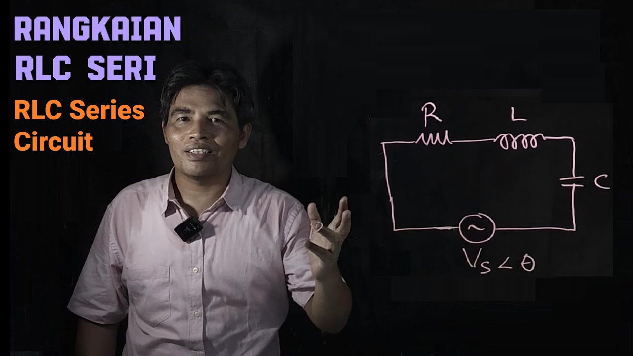
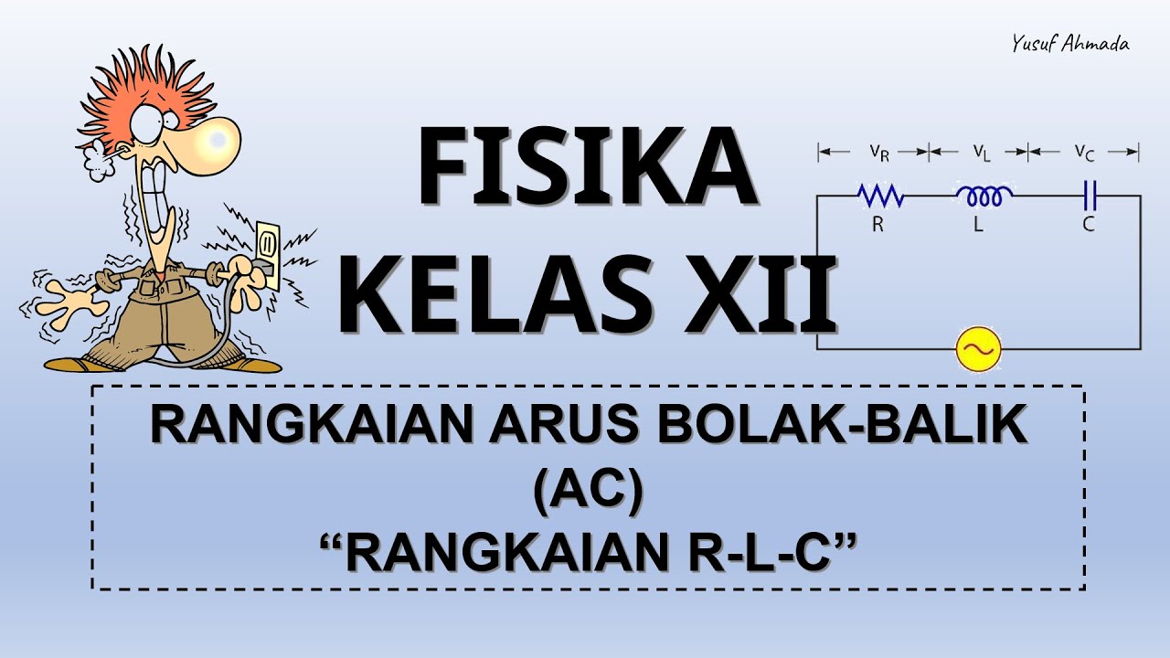
- 😀 The video covers the analysis of an RLC series circuit, which includes a resistor (R), inductor (L), and capacitor (C) connected in series.
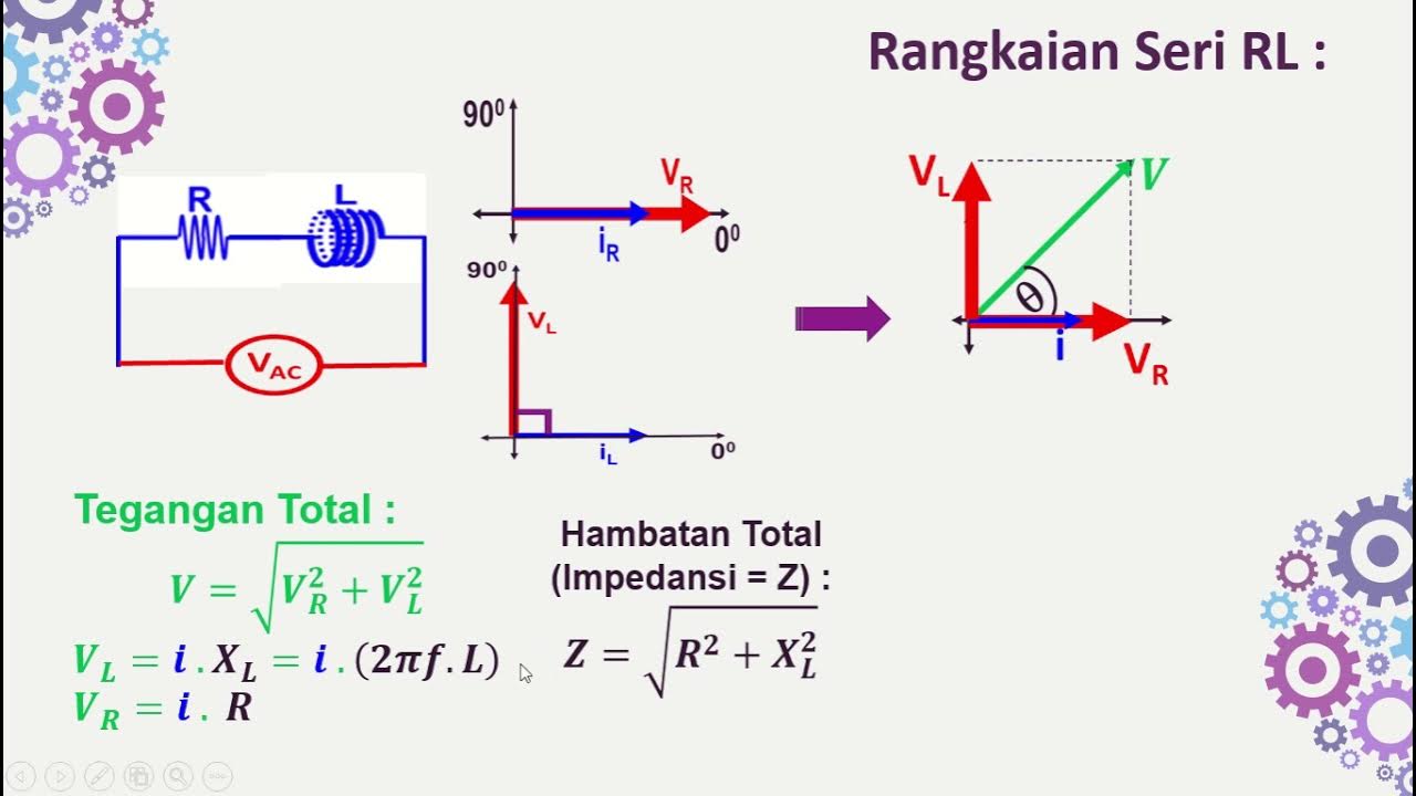
- 😀 The combined impedance (Z) of an RLC series circuit can be calculated using the formula: Z = √(R² + (XL - XC)²), where XL and XC represent the inductive and capacitive reactances respectively.
- 😀 In a series RLC circuit, the current (I) is the same across all components, making the relationship between current, voltage, and impedance straightforward.
- 😀 Ohm's Law is used to express the relationship between the current, voltage, and impedance in the circuit, where the impedance acts as an equivalent resistance for the entire RLC setup.
- 😀 Voltage across each component (R, L, C) can be calculated separately using formulas for resistive, inductive, and capacitive voltage drops.
- 😀 The phase relationship between the voltage and current is key to understanding the behavior of the circuit, with the voltage across inductors and capacitors leading or lagging the current by 90 degrees.
- 😀 The relationship between the voltage and current in the circuit can be visualized using a phasor diagram, which helps to understand the phase differences between components.
- 😀 When the inductive reactance (XL) equals the capacitive reactance (XC), the circuit is in resonance, and the impedance becomes purely resistive, leading to maximum power transfer.
- 😀 Power in an AC circuit is calculated using average power formulas, where the power factor (cosϕ) is used to relate the current and voltage magnitudes to the actual power delivered to the circuit.
- 😀 The video demonstrates how to solve an example problem involving an RLC series circuit, showing how to calculate values such as current, voltage, and phase differences using given parameters like resistance, inductance, and capacitance.
Q & A
What is an RLC series circuit?
-An RLC series circuit is a type of AC circuit that consists of a resistor (R), an inductor (L), and a capacitor (C) connected in series. The circuit has a single path for current flow, and its behavior is characterized by impedance, which is the total resistance to the flow of alternating current.
What is the impedance in an RLC series circuit?
-Impedance (Z) in an RLC series circuit is the equivalent resistance to AC current flow. It is calculated using the formula Z = √(R² + (XL - XC)²), where R is the resistance, XL is the inductive reactance, and XC is the capacitive reactance. Impedance combines the effects of resistance, inductance, and capacitance.
How do you calculate the impedance in an RLC series circuit?
-The impedance in an RLC series circuit is calculated using the formula Z = √(R² + (XL - XC)²). XL is the inductive reactance (XL = ωL), and XC is the capacitive reactance (XC = 1/(ωC)), where ω is the angular frequency (ω = 2πf), and f is the frequency of the AC signal.
What is the phase relationship between voltage and current in an RLC circuit?
-In an RLC series circuit, the phase relationship between voltage and current depends on whether the circuit is inductive, capacitive, or resonant. For an inductive circuit, the current lags the voltage by 90°. In a capacitive circuit, the current leads the voltage by 90°. At resonance, the voltage and current are in phase.
What is resonance in an RLC series circuit?
-Resonance in an RLC series circuit occurs when the inductive reactance (XL) equals the capacitive reactance (XC), i.e., XL = XC. At this point, the impedance of the circuit is purely resistive, and the current reaches its maximum value. This condition allows maximum power transfer through the circuit.
What happens to the current and voltage when the circuit is inductive?
-When the circuit is inductive, the inductive reactance (XL) dominates, causing the current to lag behind the voltage by 90°. This means the current reaches its peak after the voltage reaches its peak.
What is the power factor in an AC circuit?
-The power factor in an AC circuit is the ratio of real power (P) to apparent power (S), and it is represented by cos(φ), where φ is the phase angle between the current and voltage. It is an important factor in determining how efficiently power is used in the circuit.
How do you calculate the average power in an AC circuit?
-The average power in an AC circuit is calculated using the formula P_avg = I_RMS² * R, where I_RMS is the root mean square current and R is the resistance. Alternatively, it can be calculated as P_avg = V_RMS * I_RMS * cos(φ), where V_RMS is the root mean square voltage and φ is the phase angle between voltage and current.
What is the significance of the phase angle between voltage and current in AC circuits?
-The phase angle between voltage and current in AC circuits indicates the timing difference between the voltage and current waveforms. A phase angle of 0° means the voltage and current are in phase, while 90° means they are out of phase (current lags or leads the voltage). This phase difference affects the power factor and efficiency of the circuit.
How is the maximum current (I_max) calculated in an RLC circuit?
-The maximum current (I_max) in an RLC circuit can be calculated using the formula I_max = V_max / Z, where V_max is the maximum voltage (amplitude) of the source and Z is the impedance of the circuit. The impedance is calculated as Z = √(R² + (XL - XC)²).
Outlines

This section is available to paid users only. Please upgrade to access this part.
Upgrade NowMindmap

This section is available to paid users only. Please upgrade to access this part.
Upgrade NowKeywords

This section is available to paid users only. Please upgrade to access this part.
Upgrade NowHighlights

This section is available to paid users only. Please upgrade to access this part.
Upgrade NowTranscripts

This section is available to paid users only. Please upgrade to access this part.
Upgrade NowBrowse More Related Video


5.0 / 5 (0 votes)