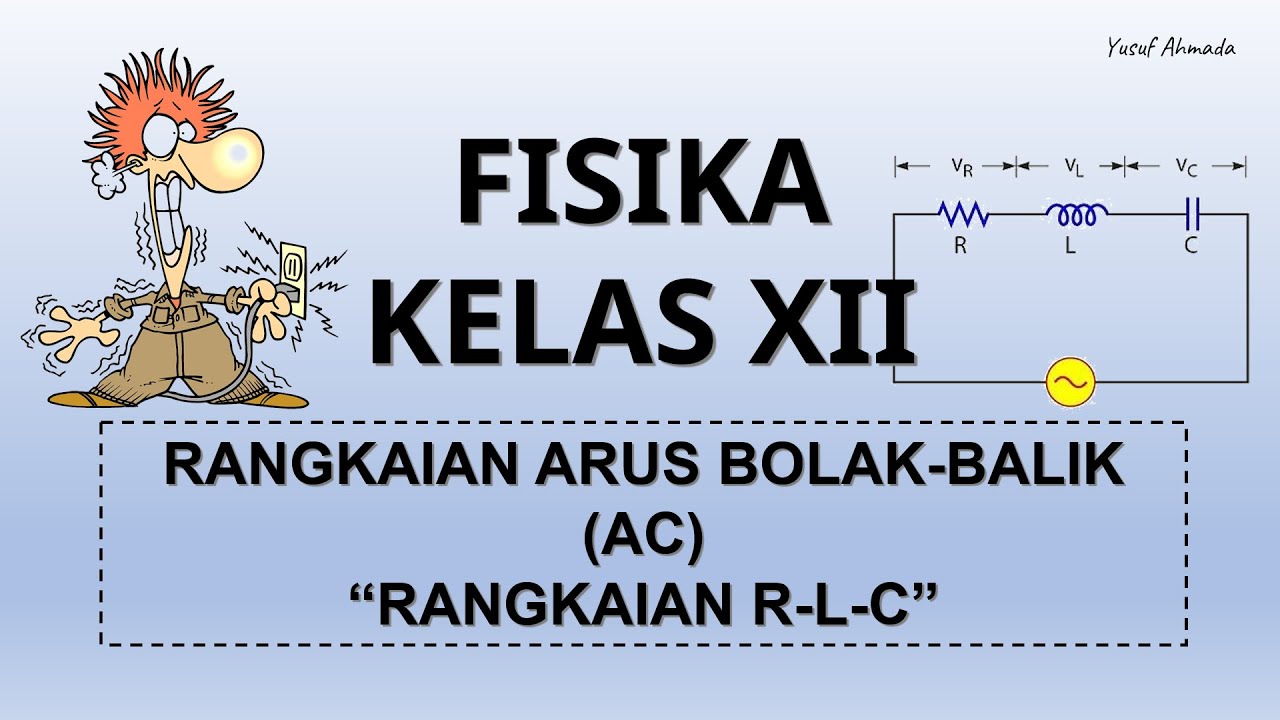
Rangkaian Seri RL-RC-LC dengan Sumber AC
Summary
TLDRThis educational video covers various AC circuit concepts, focusing on series circuits involving resistors, inductors, and capacitors (RL, RC, RLC). It explains the phase relationships between current and voltage in each component, emphasizing the use of phasor diagrams to understand these relationships. The video provides examples, including how to calculate impedance and the effects of frequency on the circuit's behavior. Practical problems are solved step-by-step, showing how to determine total voltage, current, and impedance in RL, RC, and RLC circuits, providing a comprehensive understanding of AC circuits and their applications in real-life electrical systems.
Takeaways
- 😀 The session focuses on AC circuits, specifically series circuits involving resistors, inductors, and capacitors.
- 😀 The session begins by reviewing the properties of electrical components like resistors, inductors, and capacitors when connected to an AC source.
- 😀 A key concept discussed is the use of phasor diagrams to represent voltage and current in AC circuits.
- 😀 For resistors, voltage and current are in phase, meaning no phase shift occurs between them.
- 😀 For inductors, the voltage leads the current by 90°, which is reflected in the phase shift in the phasor diagram.
- 😀 Capacitors cause the voltage to lag the current by 90°, resulting in a negative phase shift in the phasor diagram.
- 😀 Impedance is introduced as the total resistance to AC current in a circuit, calculated using the combined resistance and reactance of the components.
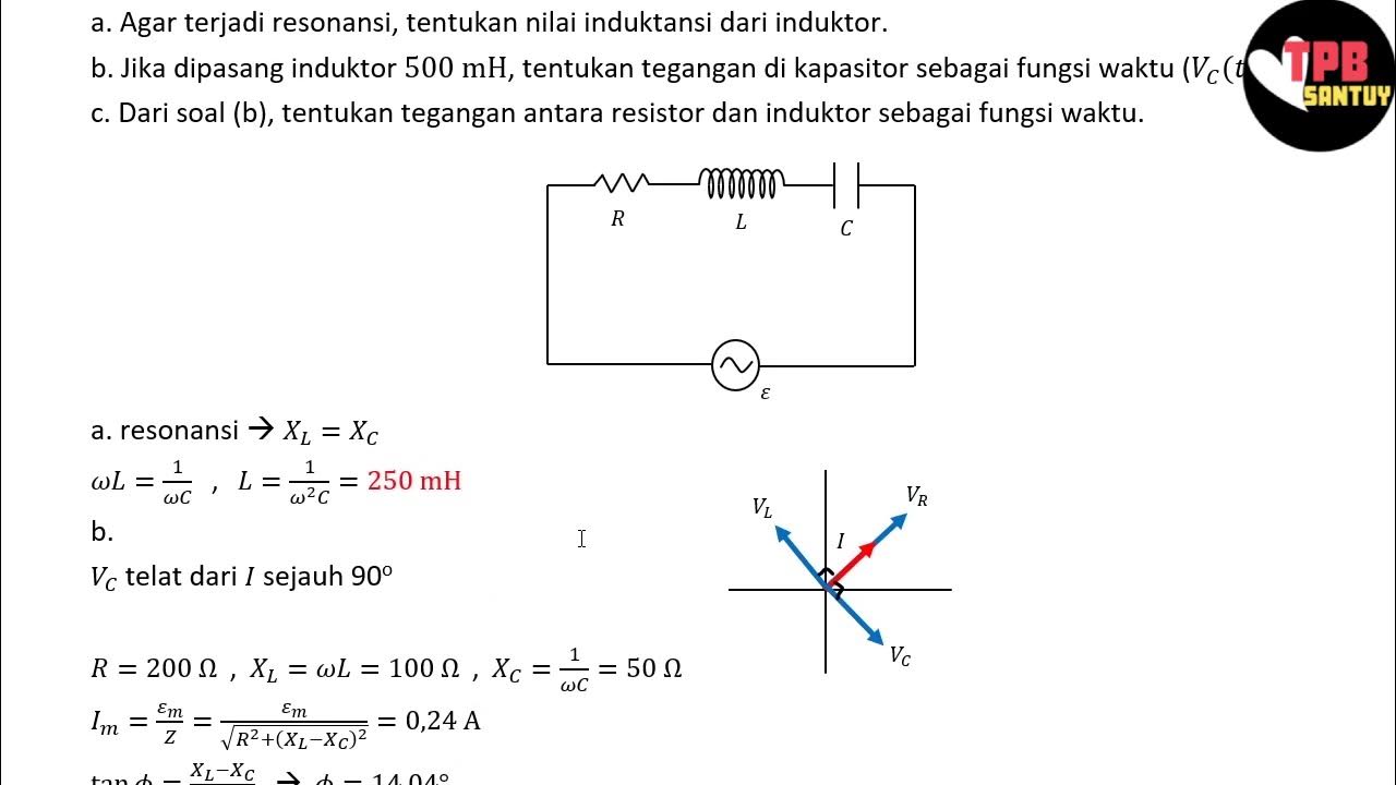
- 😀 In a series RL circuit, the total impedance is calculated using the formula: Z = √(R² + XL²), where XL is the inductive reactance.
- 😀 In a series RC circuit, impedance is calculated similarly, and the phase angle between voltage and current is influenced by the ratio of reactance to resistance.
- 😀 The session also covers solving real-life examples, such as calculating impedance, current, and voltage across components in series circuits.
- 😀 The behavior of circuits with a series combination of resistor, inductor, and capacitor is discussed, including how phase shifts and impedance are affected by each component's properties.
Please replace the link and try again.
Outlines

This section is available to paid users only. Please upgrade to access this part.
Upgrade NowMindmap

This section is available to paid users only. Please upgrade to access this part.
Upgrade NowKeywords

This section is available to paid users only. Please upgrade to access this part.
Upgrade NowHighlights

This section is available to paid users only. Please upgrade to access this part.
Upgrade NowTranscripts

This section is available to paid users only. Please upgrade to access this part.
Upgrade NowBrowse More Related Video

Electrical Engineering: Ch 8: RC & RL Circuits (1 of 43) RC & RL Circuits Introduction
FISIKA KELAS XII | RANGKAIAN ARUS BOLAK-BALIK (AC) - PART 2 : RANGKAIAN RLC
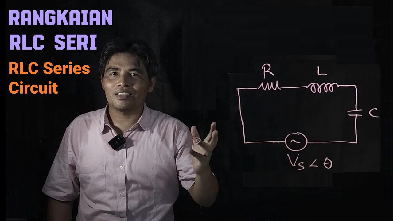
Rangkaian RLC Seri
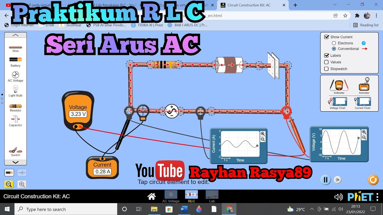
Praktikum RANGKAIAN RLC SERI PADA ARUS AC menggunakan Virtual Lab PHET.
Analisis Rangkaian AC | Rangkaian AC | Part 3 | Fisika Dasar

Análise de Circuitos - Aula 01
5.0 / 5 (0 votes)