Simulasi Resonansi RLC - Electronics Workbench
Summary
TLDRIn this video, the presenter, a student of Electrical Engineering at Universitas Negeri Jakarta, explains the workings of a series RLC circuit with AC voltage input. The key focus is on resonance, which occurs when the inductive reactance (XL) and capacitive reactance (XC) are equal at a specific frequency, causing maximum current. The video covers the setup of components like resistors, inductors, and capacitors, along with a function generator. It explains the behavior of the circuit under different reactance conditions, such as inductive, capacitive, and resistive, and includes a practical demonstration of resonance in action.
Takeaways
- 😀 The video introduces the concept of a series RLC circuit powered by an AC input.
- 😀 Resonance occurs in an RLC circuit when the inductive reactance (XL) equals the capacitive reactance (XC).
- 😀 At resonance, the current in the circuit reaches its maximum value.
- 😀 The RLC circuit consists of a resistor, an inductor, a capacitor, and a signal generator as the power source.
- 😀 Grounding is essential for the proper functioning of the RLC circuit.
- 😀 When XL is greater than XC, the circuit is inductive, and the voltage leads the current.
- 😀 When XC is greater than XL, the circuit is capacitive, and the current leads the voltage.
- 😀 At resonance, the impedance of the circuit equals the resistance of the resistor, and voltage and current are in phase.
- 😀 To calculate the inductive reactance (XL), use the formula: XL = ωL.
- 😀 To calculate the capacitive reactance (XC), use the formula: XC = 1 / (ωC).
- 😀 The frequency and amplitude of the signal generator are adjusted to observe the resonance in the RLC circuit.
Q & A
What is the main topic of the video script?
-The main topic of the video is about RLC circuits, specifically focusing on series RLC circuits and the phenomenon of resonance when subjected to an AC input voltage.
What happens at the resonant frequency in an RLC circuit?
-At the resonant frequency, the inductive reactance (XL) and capacitive reactance (XC) become equal. This results in the current becoming maximum in the circuit.
What components are needed to set up the RLC circuit in the script?
-The components required are a resistor (R), an inductor (L), a capacitor (C), a function generator (for AC input voltage), and an oscilloscope (to monitor the circuit's behavior).
What does it mean for an RLC circuit to be inductive or capacitive?
-An RLC circuit is inductive when the inductive reactance (XL) is greater than the capacitive reactance (XC), causing the voltage to lead the current. It is capacitive when XC is greater than XL, causing the current to lead the voltage.
What occurs when the inductive reactance (XL) equals the capacitive reactance (XC)?
-When XL equals XC, the circuit behaves as purely resistive, meaning the impedance is equal to the resistance, and the current and voltage are in phase.
What values were assigned to the components in the script for the circuit?
-In the script, the resistor (R) value is 100 ohms, the inductor (L) value is 120 henries, and the capacitor (C) value is 10 microfarads.
What adjustments were made to the function generator settings?
-The frequency was set to 50 Hz, and the amplitude was set to 200 V in the function generator.
How is the oscilloscope used in the setup?
-The oscilloscope is used to monitor the waveform of the circuit and to measure the voltage and current at various points, especially to identify the point of resonance where the current reaches its maximum.
What does resonance in an RLC circuit indicate about the impedance?
-At resonance, the impedance of the RLC circuit equals the resistance, meaning the total impedance is purely resistive and the current reaches its maximum value.
How can inductive and capacitive reactance be calculated?
-Inductive reactance (XL) is calculated as XL = ωL, where ω is the angular frequency and L is the inductance. Capacitive reactance (XC) is calculated as XC = 1 / (ωC), where C is the capacitance.
Outlines

This section is available to paid users only. Please upgrade to access this part.
Upgrade NowMindmap

This section is available to paid users only. Please upgrade to access this part.
Upgrade NowKeywords

This section is available to paid users only. Please upgrade to access this part.
Upgrade NowHighlights

This section is available to paid users only. Please upgrade to access this part.
Upgrade NowTranscripts

This section is available to paid users only. Please upgrade to access this part.
Upgrade NowBrowse More Related Video
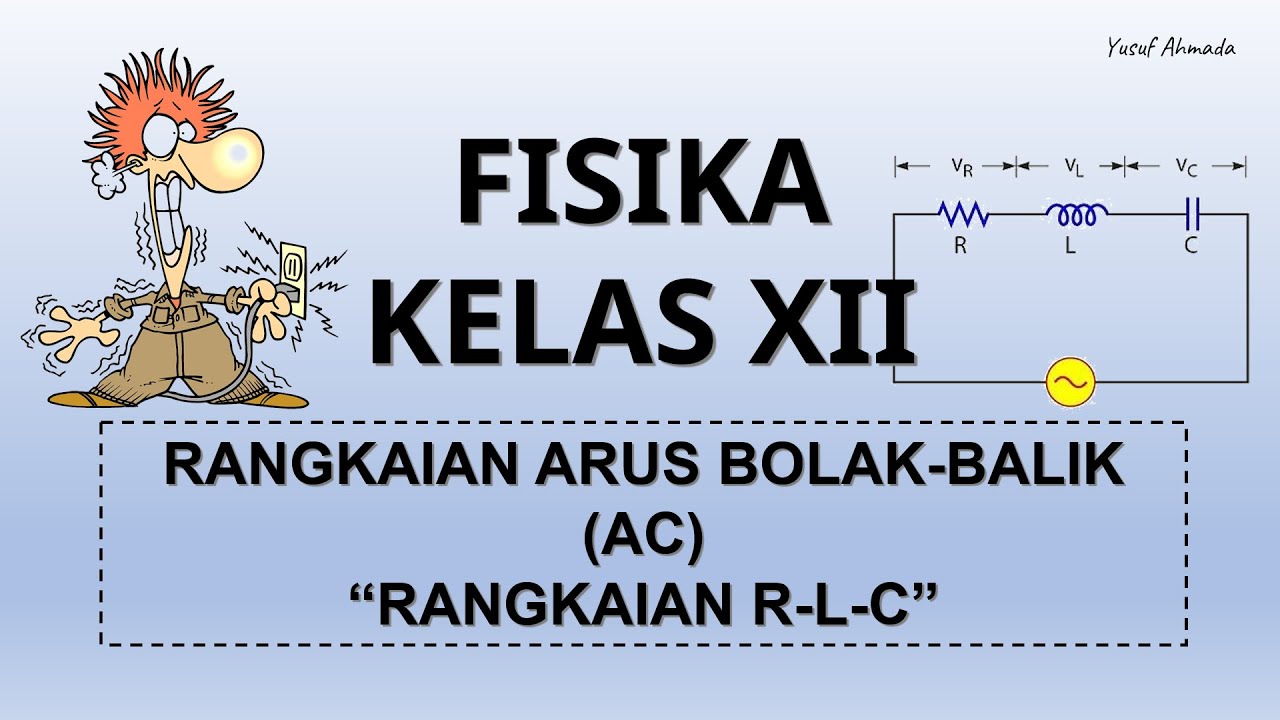
FISIKA KELAS XII | RANGKAIAN ARUS BOLAK-BALIK (AC) - PART 2 : RANGKAIAN RLC
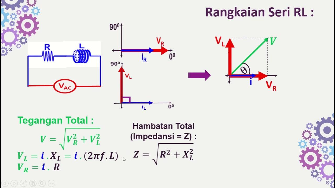
Rangkaian Seri RL-RC-LC dengan Sumber AC
AC Through Series RL Circuit - AC Circuits - Basic Electrical Engineering

Tugas Video Rangkaian Dengan Menggunakan Dioda Zener, Andi Yogi Septamikha
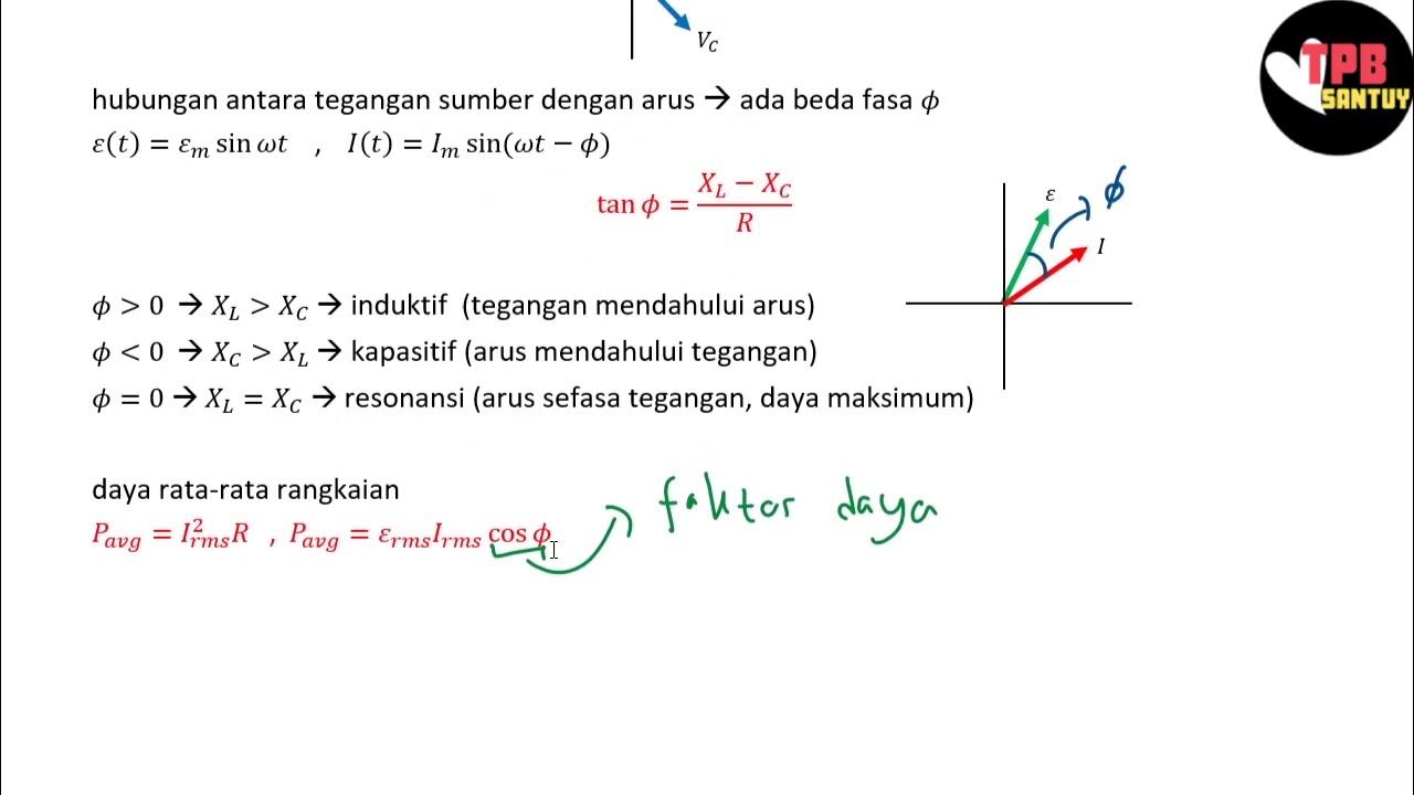
Rangkaian Seri RLC | Rangkaian AC | Part 2 | Fisika Dasar
Circuit Analysis Using Fourier Series ⭐ RL Circuit Response - Nonsinusoidal Waveform ⭐ Example 1
5.0 / 5 (0 votes)