Step-by-Step Tutorial: Setting up Bus Topology in Cisco Packet Tracer 2024 (FAST)
Summary
TLDRThis tutorial demonstrates how to create a bus topology network in Cisco Packet Tracer. The process involves adding multiple PCs using the control-click method for efficiency, connecting them with switches, and using both straight and crossover cables. The video then shows how to assign static IP addresses to two PCs and test the network connection using a ping command. The tutorial is practical, skipping the time-consuming step of assigning IPs to all PCs, and ends with a prompt to watch a related theory video and subscribe for more content.
Takeaways
- 🖥️ To create a bus topology in Cisco Packet Tracer, start by adding multiple PCs to the workspace.
- 🔗 Efficiently add PCs by holding the control key and clicking, which allows for continuous selection without needing to reselect the computer icon each time.
- 🌐 Connect the PCs using a series of switches to establish the backbone of the bus topology.
- 🔌 Utilize the autoconnect cable feature to simplify the process of connecting PCs to switches.
- 🛠️ For the main cable, ensure that the connection between switches uses a copper crossover cable, different from the straight-through cable used between PCs and switches.
- 📊 The script demonstrates a bus topology setup with a focus on practical demonstration rather than theoretical explanation.
- 💻 Assign static IP addresses to specific PCs for testing connectivity within the network.
- 📡 Use the command prompt to test network connectivity by pinging one PC from another.
- 🔍 The video provides a practical guide that assumes viewers are familiar with basic networking concepts, which are covered in a separate tutorial.
- 🎥 The tutorial is designed to be concise, focusing on the demonstration without extensive explanations, to respect the viewer's time.
Q & A
What is the first step in implementing a bus topology in Cisco Packet Tracer?
-The first step is to add a bunch of PCs to the workspace.
How can you add multiple PCs to the workspace efficiently in Cisco Packet Tracer?
-You can hold the control key and click on the PC to add it to the screen without having to select the computer again each time.
What is the purpose of adding switches in a bus topology?
-Switches are added to connect multiple PCs together with a single line, forming the backbone of the bus topology.
How do you connect PCs to switches in a bus topology?
-You use the autoconnect cable feature in Cisco Packet Tracer to connect PCs to switches.
What type of cable is used to connect switches to each other in a bus topology?
-A copper crossover cable is used to connect switches to each other in a bus topology.
Why is it necessary to move the PCs and switches to the center and clean up the layout?
-It is done to make the topology visually cleaner and easier to understand.
How many PCs are given IP addresses in the video for testing the connection?
-Only two PCs, PC26 and PC25, are given IP addresses for testing the connection.
What are the IP addresses assigned to PC26 and PC25 for testing the connection?
-PC26 is assigned the IP address 192.168.10.1 and PC25 is assigned 192.168.10.2.
How is the connection between PCs tested in Cisco Packet Tracer?
-The connection is tested by opening a command prompt and using the ping command from one PC to another.
What does a successful ping response indicate about the connection between PCs?
-A successful ping response indicates that there is a stable and functioning connection between the PCs.
Where can viewers find more information about network topologies?
-Viewers can find more information about network topologies in another tutorial, the link to which is provided in the video description.
Outlines

This section is available to paid users only. Please upgrade to access this part.
Upgrade NowMindmap

This section is available to paid users only. Please upgrade to access this part.
Upgrade NowKeywords

This section is available to paid users only. Please upgrade to access this part.
Upgrade NowHighlights

This section is available to paid users only. Please upgrade to access this part.
Upgrade NowTranscripts

This section is available to paid users only. Please upgrade to access this part.
Upgrade NowBrowse More Related Video

Basics of Cisco Packet Tracer (Part 2) | Hub
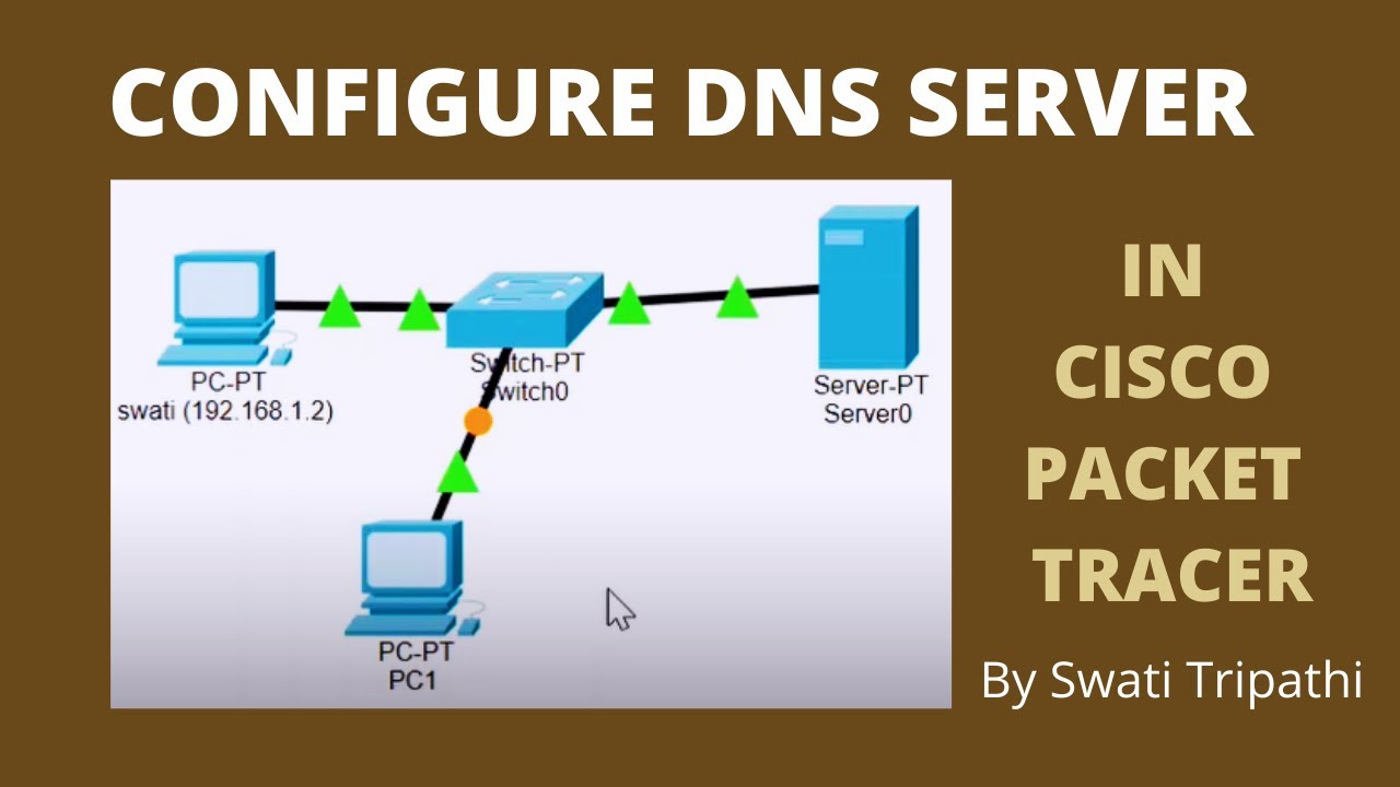
DNS Server Configuration in Cisco Packet Tracer
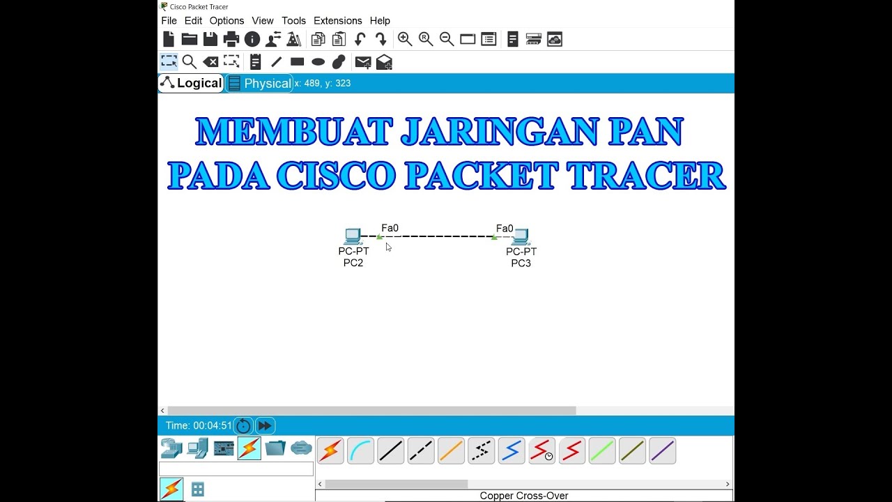
Membuat Jaringan PAN pada Cisco Packet Tracer

Konfigurasi Mudah DHCP SERVER di Cisco Packet Tracert dengan 1 Server 1 Switch 3 Client

Netzwerktutorial: Cisco Packet Tracer - Installation, Konfiguration & ein erster Aufbau
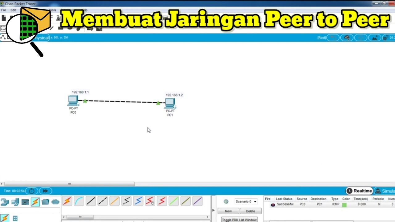
Cara Membuat Jaringan Peer To Peer di Cisco Packet Tracer
5.0 / 5 (0 votes)