Ladder Logic Diagrams for PLCs | Industrial Automation
Summary
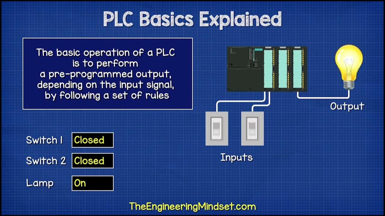
TLDRThis video introduces the fundamentals of programming PLCs (Programmable Logic Controllers) using ladder logic diagrams. It explains how ladder logic mimics electrical circuits for easier understanding by engineers and technicians. The video covers essential concepts like the structure of ladder diagrams, logical operations (AND, OR, NOT), and more advanced techniques such as latching and sequencing. Additionally, it outlines the importance of standardizing programming languages for PLCs, as well as providing practical examples of controlling motors and actuators. The series prepares learners to implement these diagrams on a PLC simulator for real-world applications.
Takeaways
- 😀 Ladder Logic is a widely-used programming language for PLCs (Programmable Logic Controllers) that is closely related to electrical diagrams, making it easier for engineers and technicians to understand and implement.
- 😀 In 1993, the IEC standardized PLC programming languages, including Ladder Logic, Instruction List, Sequential Function Charts, Structured Text, and Function Block Diagrams, making PLC programming more uniform across manufacturers.
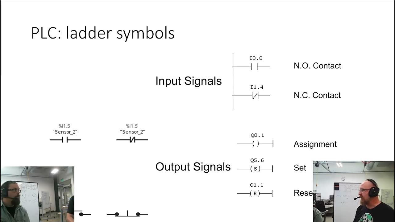
- 😀 Ladder Logic diagrams consist of vertical lines (power rails) and horizontal lines (rungs) that represent electrical circuits, with inputs typically placed on the left and outputs on the right.
- 😀 Components in Ladder Logic diagrams should always be shown in their normal states. For example, normally open switches are shown as open, while normally closed switches are shown as closed.
- 😀 Rungs represent actions in Ladder Logic. A simple rung may include a switch in series with an output coil, which controls the activation of an output when the switch is pressed.
- 😀 PLC components in Ladder Logic diagrams must be addressed correctly. Each component, whether an input or output, must have a specific address format, which varies depending on the PLC manufacturer (e.g., Mitsubishi, Siemens, Allen Bradley).
- 😀 Logical operations such as AND, OR, and NOT can be implemented in Ladder Logic by connecting switches and contacts in specific ways, allowing for complex control systems.
- 😀 The AND operation in Ladder Logic requires both input conditions to be true for the output to be activated, such as a system that starts a motor only when both switches are closed.
- 😀 Latching is a technique in Ladder Logic that keeps an output in its activated state even after the input is no longer active, until a second input is used to deactivate it.
- 😀 Sequencing in Ladder Logic allows multiple outputs to be activated in a defined sequence, with each output requiring the activation of specific inputs in order.
- 😀 Complex applications of Ladder Logic, such as controlling motors, lights, and other actuators, can be easily implemented using combinations of switches, logical functions, and advanced techniques like latching and sequencing.
Q & A
What is ladder logic, and why is it used in PLC programming?
-Ladder logic is a graphical programming language used for PLC programming that mimics electrical circuits. It is widely used because it is intuitive and resembles the electrical diagrams that engineers and technicians are familiar with, making it easier to understand and troubleshoot on the factory floor.
How are PLC inputs and outputs represented in ladder logic diagrams?
-In ladder logic, PLC inputs are typically placed on the left side, while outputs are placed on the right side. The diagram is structured with vertical power rails on the left (high voltage) and right (low voltage), with horizontal rungs in between that contain the components like switches and coils.
What is the purpose of power rails in ladder logic?
-Power rails in ladder logic are vertical lines that represent the high and low voltage points of the circuit. The high voltage rail is on the left side, while the low voltage rail is on the right side. These rails provide the electrical flow through the components represented in the rungs.
What are the different types of contacts in ladder logic, and how do they function?
-The two primary types of contacts in ladder logic are normally open (NO) and normally closed (NC) contacts. A NO contact is shown as open and closes when activated, allowing power to flow. A NC contact is shown as closed and opens when activated, interrupting the power flow.
What does it mean to 'latch' an output in a ladder logic diagram?
-Latching an output in a ladder logic diagram means holding the output state even after the input condition has been removed. This is done by using a parallel contact connected to the output coil, which keeps the coil energized even when the initial input is turned off.
What logical operations can be implemented using ladder logic?
-Ladder logic can implement several logical operations, such as AND, OR, NOT, NAND, NOR, and XOR. These operations are represented by various configurations of normally open and normally closed contacts in the rungs of the diagram.
How is an AND operation implemented in a ladder diagram?
-An AND operation is implemented in ladder logic by connecting two contacts in series. The output coil is energized only when both input conditions (contacts) are true, meaning both switches must be closed to allow power to flow through the output coil.
What is sequencing in ladder logic, and why is it used?
-Sequencing in ladder logic involves controlling multiple outputs in a specific order. It is used in situations where outputs must be turned on in a defined sequence, though turning them off doesn’t require a specific order. This is achieved by arranging inputs in a hierarchical structure within the rungs.
What are the advantages of using ladder logic over other programming languages for PLCs?
-Ladder logic is preferred for PLC programming because it is visually intuitive, easy to understand for factory technicians, and closely resembles the electrical circuits they already work with. It simplifies the process of programming and troubleshooting without requiring complex coding skills.
How does addressing work in PLC ladder logic programming?
-Addressing in PLC ladder logic involves assigning specific addresses to each input and output device so that the PLC can correctly interact with the physical hardware. Different manufacturers may use different addressing formats, but the ladder logic diagram remains the same across platforms.
Outlines

Cette section est réservée aux utilisateurs payants. Améliorez votre compte pour accéder à cette section.
Améliorer maintenantMindmap

Cette section est réservée aux utilisateurs payants. Améliorez votre compte pour accéder à cette section.
Améliorer maintenantKeywords

Cette section est réservée aux utilisateurs payants. Améliorez votre compte pour accéder à cette section.
Améliorer maintenantHighlights

Cette section est réservée aux utilisateurs payants. Améliorez votre compte pour accéder à cette section.
Améliorer maintenantTranscripts

Cette section est réservée aux utilisateurs payants. Améliorez votre compte pour accéder à cette section.
Améliorer maintenantVoir Plus de Vidéos Connexes
SysAp 7 1 Ladder Logic
PLC: convertire lo schema elettrico funzionale in linguaggio di programmazione Ladder (Video 1.1)
Belajar PLC | Pengenalan Programmable Logic Controller #1
PLC Basics | Programmable Logic Controller

AWAL BELAJAR Ngobrol Santai Tentang PLC (Programmable Logic Controller)
1. Berkenalan Dengan Kerja Perangkat Kontrol PLC
5.0 / 5 (0 votes)
