Mechanics of Materials: F1-1 (Hibbeler)
Summary
TLDRThis video script details a structural engineering problem involving a beam with specific support conditions and loadings. The focus is on calculating the internal normal force, shear force, and bending moment at Point C. The process involves drawing a free-body diagram, applying global equilibrium for overall system analysis, and determining reaction forces at supports A and B. The script then proceeds to find the internal forces at Point C by making an appropriate cut and analyzing the left side of the beam for normal force, shear force, and bending moment. The final results indicate a zero normal force, a shear force of 20 kN, and a bending moment of -40 kNm at Point C.
Takeaways
- 📏 The problem involves determining the normal force (N), shear force (V), and bending moment (M) at Point C of a beam.
- 🏗️ The beam is supported by a roller at A to the left of C and a pin at B to the right of C.
- ⚙️ A 60 kNm moment acts on the left end of the beam, and a 10 kN downward force acts on the right.
- 📈 The first step is to draw a free-body diagram of the entire system, including the forces and moments acting on the beam.
- 🔍 To find the reaction forces (Ay and By), moments are taken about point A, leading to the calculation of By as -10 kN.
- 📉 The normal force at C (NC) is found to be zero by considering the equilibrium in the X direction.
- 📊 The shear force at C (VC) is calculated to be 20 kN by summing forces in the Y direction.
- 📐 The bending moment at C (MC) is determined by summing moments about point C, resulting in -40 kNm.
- 🔧 The analysis uses the principles of statics to solve for the internal forces in the beam.
- 📋 The process involves making appropriate cuts in the beam to analyze the internal effects and applying the equations of equilibrium.
Q & A
What are the three internal forces to be determined in the beam at Point C?
-The three internal forces to be determined at Point C are the normal force (N), shear force (V), and bending moment (M).
What are the boundary conditions of the beam described in the script?
-The beam is supported by a roller at A to the left of C and a pin at B to the right of C.
What are the external forces and moments acting on the beam?
-There is a 60 kilonewton-meter moment acting on the left end of the beam and a downward 10 kilonewton force on the right.
How is the free-body diagram of the beam constructed?
-The free-body diagram includes the beam, the 10 kilonewton force, and the moment on the left, with vertical reaction forces at A and B, and dimensions noted.
Why are moments used to find the reaction forces instead of the sum of forces?
-Moments are used because there are two unknown reaction forces (Ay and By), and using moments allows solving for one of them without having two unknowns in a single equation.
What is the method used to find the reaction force By?
-The reaction force By is found by taking moments about point A and solving the equation for By.
What is the calculated value of By and why is it negative?
-The calculated value of By is -10 kilonewtons, which is negative because the force is acting downwards, opposite to the chosen positive direction.
How is the normal force at Point C determined?
-The normal force at Point C is determined to be zero by setting the sum of forces in the x-direction equal to zero, as there are no external forces acting in that direction.
What is the shear force VC at Point C?
-The shear force VC at Point C is 20 kilonewtons, found by setting the sum of forces in the y-direction equal to zero.
How is the bending moment MC at Point C calculated?
-The bending moment MC at Point C is calculated by summing moments about Point C, considering the applied moments and forces, resulting in -40 kilonewton-meters.
What is the significance of the negative bending moment MC?
-A negative bending moment MC indicates that the beam is bending in a clockwise direction when viewed from the left end of the beam.
Outlines

Esta sección está disponible solo para usuarios con suscripción. Por favor, mejora tu plan para acceder a esta parte.
Mejorar ahoraMindmap

Esta sección está disponible solo para usuarios con suscripción. Por favor, mejora tu plan para acceder a esta parte.
Mejorar ahoraKeywords

Esta sección está disponible solo para usuarios con suscripción. Por favor, mejora tu plan para acceder a esta parte.
Mejorar ahoraHighlights

Esta sección está disponible solo para usuarios con suscripción. Por favor, mejora tu plan para acceder a esta parte.
Mejorar ahoraTranscripts

Esta sección está disponible solo para usuarios con suscripción. Por favor, mejora tu plan para acceder a esta parte.
Mejorar ahoraVer Más Videos Relacionados

SFD and BMD - Problem 1 - Part 1 - Shear Force and Bending Moment Diagram - Strength of Materials
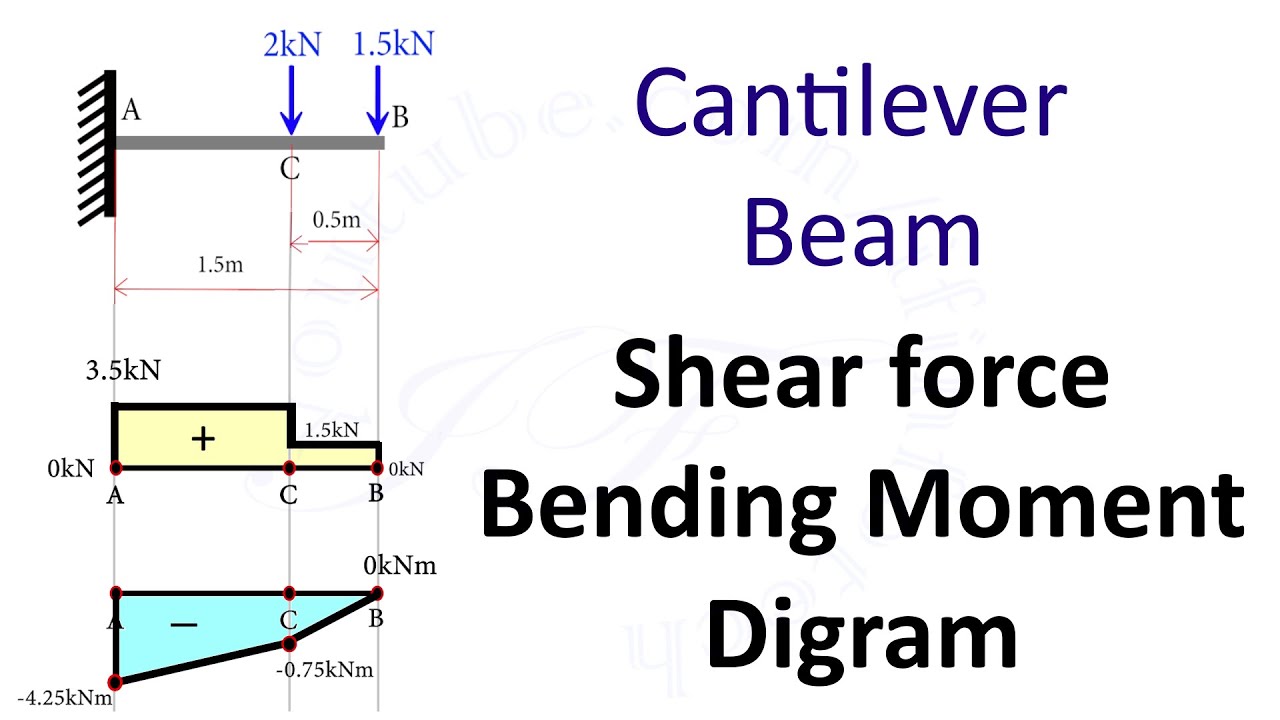
Cantilever Beam: Shear Force and Bending Moment Diagram [SFD BMD Problem 2] By Shubham Kola

Balok Penampang T SNI 2847-2019

[Struktur Baja 2]: Perhitungan Sambungan Balok-Kolom Baja
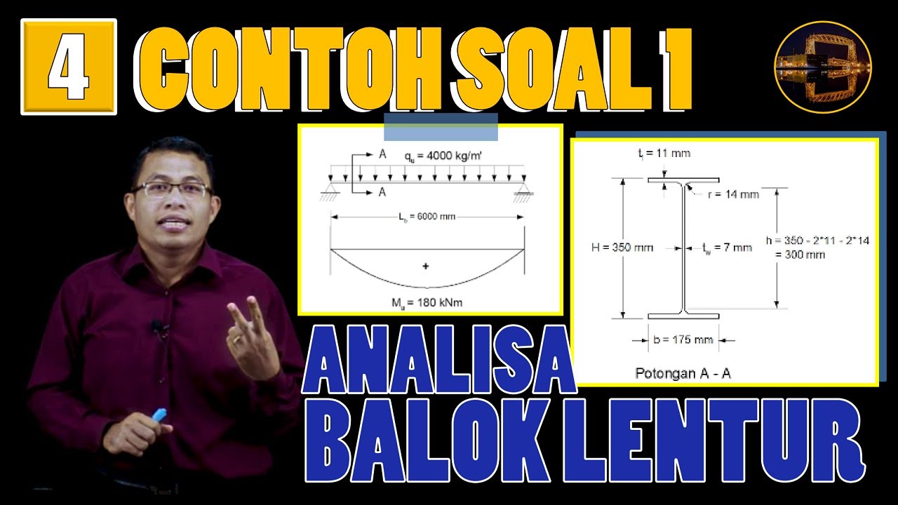
Contoh Perhitungan Analisa Balok Anak dgn Plastik Sempurna (Leleh Umum) | Struktur Baja | Lightboard
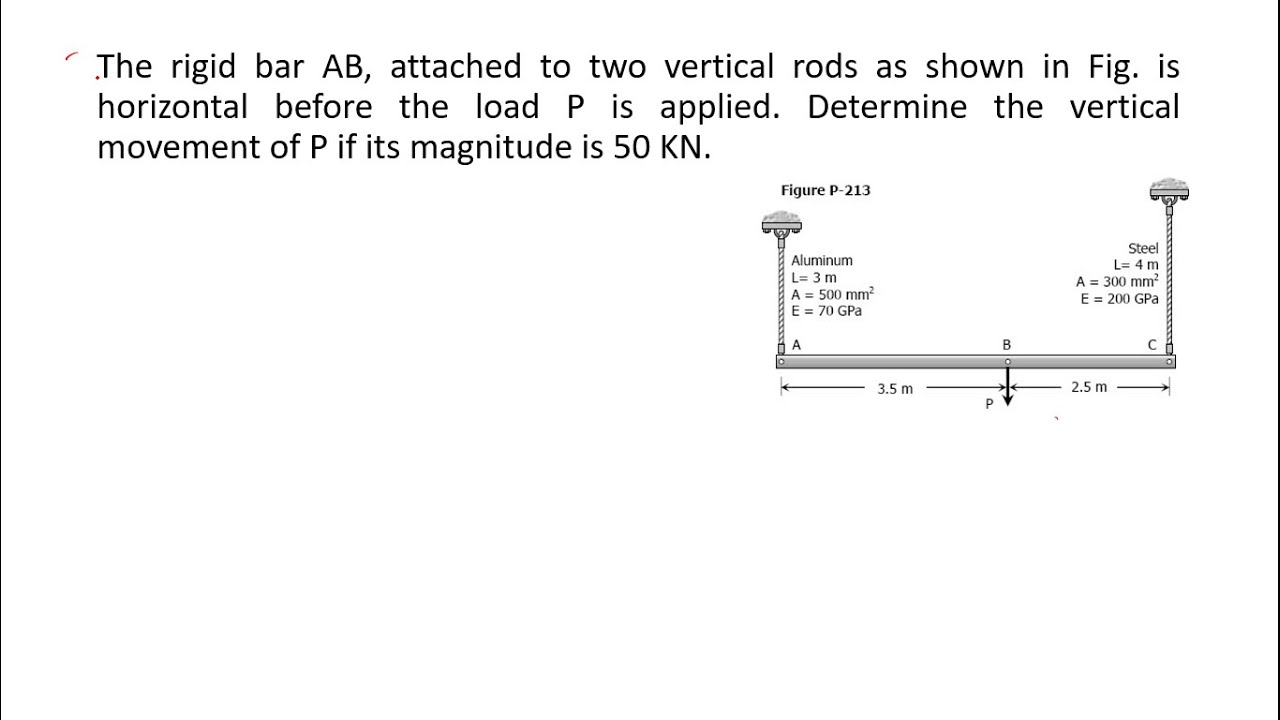
The rigid bar AB, attached to two vertical rods as shown in
5.0 / 5 (0 votes)
