Latches and Flip-Flops 2 - The Gated SR Latch

Computer Science
23 Jun 201809:33

Summary

TLDRThis script explains the concept of a gated SR latch, an advanced version of the basic SR latch, which can only change state when enabled. It uses the analogy of an air conditioning system to illustrate how each room's cooling unit can be independently controlled by its own SR latch. The video describes how to convert a regular SR latch into a gated one by adding AND or NAND gates, creating an additional 'enable' input. It also introduces the symbol for a gated SR latch and uses timing diagrams to demonstrate its behavior, highlighting its utility in various applications.

Takeaways

  • 🔒 A gated SR latch is an SR latch with an additional 'enable' functionality, allowing it to change state only when enabled.
  • 🏢 The concept is illustrated with an air conditioning system, where each room's cooling unit is controlled by an SR latch with set/reset signals from sensors.
  • 🔄 An SR latch is level-sensitive, meaning it responds to the level of the input signal (high or low) rather than the duration of the pulse.
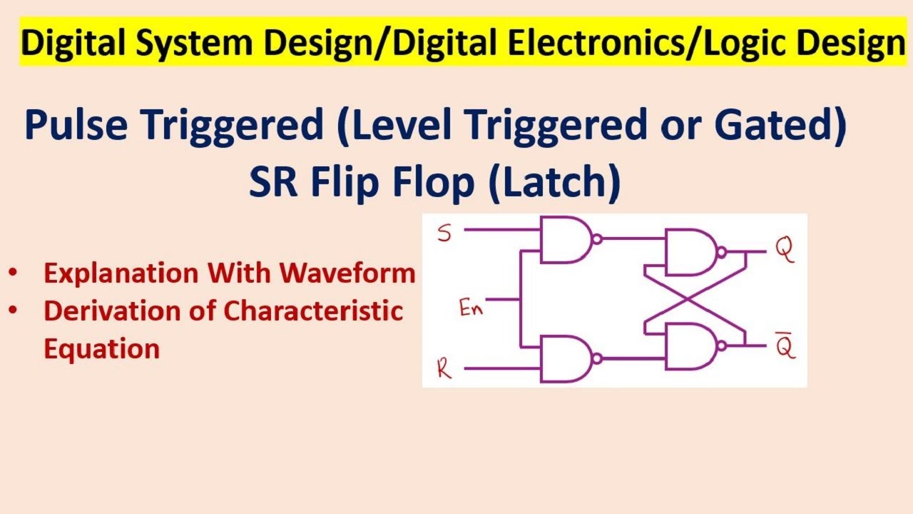
  • 🛠️ To create a gated SR latch, AND gates are added to an SR latch built from NOR gates, or additional NAND gates are added for one built from NAND gates.
  • 🔄 The addition of gates changes the latch from active low to active high, depending on the type of gates used (NOR or NAND).
  • 🚫 It's invalid for both S and R inputs to be high at the same time in an SR latch.
  • 🔑 The third input 'E' in a gated SR latch is crucial as it enables or disables the latching effect.
  • 📊 The behavior of a latch can be visualized using a timing diagram, which shows changes in voltage over time for each input and the output.
  • 🔄 The normal states of S and R are reversed when transforming an active low latch into an active high latch using additional gates.
  • 🔄 The term 'steering gates' refers to the additional gates that create the gated functionality in an SR latch.
  • 👁️ A transparent latch allows input to affect the output unconditionally, whereas a gated SR latch is transparent only when enabled.

Q & A

  • What is a gated set/reset latch?

    -A gated set/reset latch is an SR latch that can only change state when it is enabled. It incorporates an additional input, 'E', which acts as an enable signal to control the latching effect.

  • How can a gated SR latch be used in an air conditioning system?

    -In an air conditioning system, each room could have its own cooling unit controlled by an SR latch. The set and reset signals might come from temperature or humidity sensors, and a central control panel could enable or disable these units on a room-by-room basis.

  • What is an active high SR latch?

    -An active high SR latch is one that requires a high pulse (1) at input S to set the latch and a high pulse at input R to reset it, resulting in a high output at Q.

  • What does it mean for an SR latch to be level sensitive?

    -A level-sensitive SR latch responds to a valid change in either S or R, regardless of the duration of the input pulse. It is the level (high or low) that matters, not the duration of the input.

  • How can an SR latch be made into a gated SR latch?

    -A regular SR latch can be turned into a gated SR latch by connecting a pair of AND gates in series with the inputs of an OR-based SR latch, or by adding another pair of NAND gates to a NAND-based SR latch.

  • What is the purpose of the steering gates in a gated SR latch?

    -Steering gates, which are the additional AND or NAND gates in a gated SR latch, control the transparency of the latch. They determine whether the latch will respond to changes in S or R inputs only when enabled.

  • What is the difference between a transparent and a gated SR latch?

    -A transparent SR latch is one where a valid input will affect the output unconditionally. A gated SR latch, on the other hand, is transparent only when it is enabled by the additional input E.

  • What symbol is used to represent a gated SR latch in diagrams?

    -A gated SR latch has its own symbol that simplifies diagrams, showing inputs SE and R, the output Q, and its inverse, to focus on what the latch does rather than the internal components.

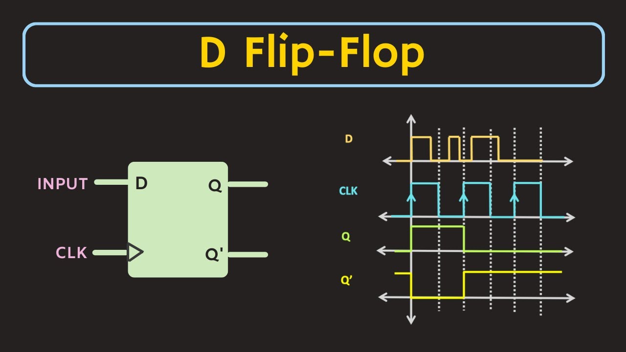
  • How can the behavior of a latch be described using a timing diagram?

    -The behavior of a latch can be described using a timing diagram that shows changes in voltage against time for each input (S, R, E) and the output Q, allowing visualization of the circuit's operation over time.

  • How does the enable input 'E' affect the behavior of a gated SR latch?

    -The enable input 'E' determines whether the gated SR latch will respond to changes in S or R. If 'E' is high, the latch is enabled and will change state based on S and R inputs; if 'E' is low, the latch is disabled and will not respond to S or R inputs.

  • What is the significance of the transition time in a digital circuit?

    -The transition time, which is the time it takes for the voltage to change from low to high or vice versa, is significant in digital circuits. Although it is assumed to be instantaneous in the script for simplicity, in reality, it takes a few nanoseconds and can affect circuit performance.

Outlines

00:00

🔒 Understanding Gated SR Latches

This paragraph introduces the concept of a gated set/reset latch, which is a type of SR latch that can change state only when enabled. It uses the analogy of an air conditioning system to explain how each room's cooling unit can be independently controlled by its own SR latch. The set and reset signals could be derived from temperature or humidity sensors, with a central control panel managing the enabling or disabling of these units. The paragraph explains the difference between an active high and active low SR latch, the importance of not applying high pulses to both S and R simultaneously, and the concept of level sensitivity. It then describes how to enhance a basic SR latch by adding AND or NAND gates to create a gated SR latch, which introduces a third input E for enabling or disabling the latching effect. The paragraph also discusses the idea of transparency in latches and introduces the symbol for a gated SR latch, emphasizing the use of timing diagrams to illustrate the behavior of the latch.

05:04

📊 Visualizing Gated SR Latch Operation

The second paragraph delves into the visualization of a gated SR latch's operation through timing diagrams. It explains how to stack multiple charts for each input (S, R, D) and the output (Q) along a common time axis to observe the circuit's behavior. The paragraph describes the normal latching behavior when the enable input E is high and how the latch behaves like a simple SR latch without steering gates in this case. It then discusses the effects of varying the E input, showing how the latch responds when E is high and becomes non-responsive when E is low. The summary highlights the transformation of an SR latch built from NOR gates into a gated SR latch by adding AND gates, and similarly, the conversion of an SR latch built from NAND gates into a gated SR latch by adding additional NAND gates, which also changes it from active low to active high. The paragraph concludes by emphasizing the gated SR latch's additional input E, which must be high for the latch to respond to changes in S or R, and the use of its own symbol to simplify circuit diagrams.

Mindmap

Keywords

💡Gated Set/Reset Latch

A gated set/reset latch, also known as a gated SR latch, is a type of latch in digital circuitry that can only change state when enabled. It is an extension of the basic SR (Set/Reset) latch with an additional control input. In the context of the video, this concept is used to explain how an air conditioning system could be controlled with independent units in each room, where the set and reset signals might come from temperature or humidity sensors. The gated aspect allows for central control over the activation of these units.

💡SR Latch

An SR latch, or Set/Reset latch, is a fundamental building block in digital electronics that maintains its state until explicitly changed. It is composed of two cross-coupled logic gates. The video explains that an SR latch built from NOR gates is an active high latch, requiring a high pulse to set or reset. This concept is foundational to understanding the more complex gated SR latch.

💡Active High

In digital electronics, 'active high' refers to a system where a high voltage level (typically a '1') is required to trigger a particular action or state change. The video uses this term to describe the behavior of an SR latch built from NOR gates, where a high pulse is needed to set or reset the latch.

💡Level Sensitive

A level-sensitive latch responds to the level (high or low) of the input signal, rather than the edges (transitions from high to low or vice versa). The video explains that an SR latch is level sensitive, meaning it will respond to a valid change in the input signal regardless of the duration of the input pulse.

💡Steering Gates

Steering gates are additional gates used in a gated SR latch to control the flow of signals. They determine whether the latch will be enabled or disabled. The video describes how by adding AND gates to an SR latch, these steering gates create an additional input 'E' that controls the latching effect.

💡Transparent Latch

A transparent latch is one where the output immediately reflects the current input state. The video mentions that an SR latch without steering gates is transparent, meaning a valid input will affect the output without any delay or condition. This is contrasted with a gated SR latch, which only behaves transparently when enabled.

💡NAND Gates

NAND gates are logic gates that produce an output that is false only when all inputs are true. The video explains how an SR latch built from NAND gates can be modified to become a gated SR latch by adding another pair of NAND gates, which also changes it from an active low to an active high latch.

💡Enable Input (E)

The enable input 'E' is a control signal that determines whether the gated SR latch will respond to the set or reset inputs. The video describes that for a gated SR latch to operate, the enable input must be high, allowing the latch to change state in response to changes in S or R.

💡Timing Diagram

A timing diagram is a graphical representation of the changes in voltage or signal levels over time in a digital circuit. The video uses timing diagrams to illustrate the behavior of a gated SR latch, showing how the output Q changes in relation to the inputs S, R, and E over time.

💡Binary Value

In digital systems, a binary value represents data as a sequence of 0s and 1s. The video mentions that the voltage levels in a digital circuit, either low (representing binary zero) or high (representing binary one), are crucial for the operation of latches and other digital components.

Highlights

A gated set/reset latch is an SR latch with an additional 'enable' functionality.

The enable feature allows for central control over individual units, such as in a building's air conditioning system.

An SR latch is level-sensitive, responding to the level of the input signal rather than the duration.

An SR latch can be built using NOR gates, requiring a high pulse at input S to set and at R to reset.

It is invalid for both S and R to be high simultaneously in an SR latch.

Gated SR latches can be created by adding AND gates to an SR latch, enabling control over the latching effect.

An SR latch built with NAND gates is active low, requiring a low pulse to set or reset.

Adding NAND gates to a NAND-based SR latch changes it from active low to active high.

The additional gates in a gated SR latch are sometimes called steering gates.

A gated SR latch is transparent only when enabled, unlike a non-gated latch which is always transparent.

A gated SR latch has its own symbol for simplified diagram representation.

The behavior of a latch can be visualized using a timing diagram showing voltage changes over time.

A level-sensitive gated SR latch's time intervals can vary greatly depending on the application.

The voltage transition in a digital circuit is assumed to be instantaneous for simplification.

The classic square wave representation is used to describe the behavior of a latch in a timing diagram.

Stacking timing diagrams allows for a comprehensive visualization of a latch's operation over time.

The enable input E must be high for a gated SR latch to respond to changes in S or R.

The behavior of a gated SR latch is demonstrated through its response to variations in the enable signal E.

A gated SR latch maintains its state when disabled, not responding to input changes.

Transcripts

play00:00

a gated set/reset latch is an SR latch

play00:06

that can only change state while it's

play00:09

enabled for example imagine an air

play00:12

conditioning system in the building

play00:14

each room could have its own cooling

play00:16

unit controlled independently by its own

play00:18

SR latch the set and reset signals might

play00:22

come from a temperature sensor or a

play00:24

humidity sensor in the room if these

play00:28

were gated SR latches then a central

play00:31

control panel could be used to enable or

play00:33

disable the switching on and off of

play00:35

these units on a room-by-room basis

play00:40

here's an uncoated SR latch remember an

play00:44

SR latch built from nor gates like this

play00:47

one is an active high SR latch this

play00:51

means it requires a high pulse that's a

play00:53

1 to be applied at input s in order to

play00:56

get a high output at Q in other words to

play00:59

set the latch alternatively to reset the

play01:03

latch and make the output at Q 0 it

play01:06

requires a high pulse to be applied to

play01:08

input R it's invalid for both s and R to

play01:13

be made high at the same time an SR

play01:18

latch is said to be level sensitive this

play01:21

means it will respond to a valid change

play01:23

in either S or R regardless of the

play01:26

duration of the input pulse it's the

play01:29

level high or low that matters not how

play01:31

long it's applied for to build a gated

play01:35

SR latch

play01:36

we can make some simple enhancements to

play01:38

an SR latch by connecting a pair of and

play01:41

gates in series with the inputs of an or

play01:44

based SR latch we've created a third

play01:46

input e which can be used to enable or

play01:49

disable the latching effect a regular

play01:53

and gate will only have a high output if

play01:55

both inputs are high so only when e is

play01:58

set to one with a one from s or a one

play02:01

from our get through to our cross

play02:03

connected nor gates here's an SR latch

play02:08

built from NAND gates this is a

play02:12

of sensitive active low sr latch in

play02:16

other words both S&R are normally high

play02:19

and it requires a low pulse that's a

play02:21

zero to be applied to s in order to set

play02:24

it it also requires a low pulse to be

play02:27

applied to R in order to reset it by

play02:31

connecting an extra pair of NAND gates

play02:33

to the latch like this not only have we

play02:36

created a third input e we now have a

play02:39

new circuit in which the normal states

play02:42

of s and r are zero and high pulses are

play02:45

required to set or reset the latch in

play02:48

other words our NAND based latch has

play02:51

been changed from an active low latch

play02:53

into an active high latch these

play03:00

additional gates on a basic SR latch are

play03:03

sometimes referred to as steering gates

play03:06

an SR latch without steering gates is

play03:09

said to be transparent a valid input

play03:13

will affect the output unconditionally a

play03:16

gated SR latch on the other hand is

play03:18

transparent only when it's enabled it's

play03:23

convenient to give a gated SR latch its

play03:26

own symbol because we can now focus on

play03:28

what the latch does rather than what's

play03:30

going on inside it the inputs SE and r

play03:34

are still shown and so is the output q

play03:36

and its inverse not cute

play03:47

we can illustrate what's going on at any

play03:49

one of the inputs or the output on a

play03:52

chart showing changes in voltage against

play03:55

time at any given moment the voltage

play03:58

will be either low zero volts to all

play04:00

intents and purposes and representing

play04:03

the binary value zero or high at about

play04:06

five volts representing the binary value

play04:08

one now of course everything can happen

play04:12

very quickly in a digital circuit each

play04:15

time interval on this chart could be in

play04:17

the order of a microsecond that's a

play04:19

millionth of a second

play04:21

having said that for a level sensitive

play04:23

gated SR latch each time interval might

play04:26

be one second or one minute or even an

play04:28

hour it really depends on the

play04:30

application for the purposes of this

play04:33

discussion it takes no time for the

play04:36

voltage to change from low to high or

play04:38

from high to low in reality this

play04:42

transition takes a few nanoseconds the

play04:45

significance of which we'll ignore for

play04:46

now but come back to in a later video

play04:48

let's proceed on the assumption that

play04:51

switching from low to high or vice-versa

play04:53

is instantaneous this gives us the

play04:56

classic square wave that you can see

play04:58

here we now have a convenient way to

play05:04

describe the behavior of a latch by

play05:07

stacking several charts together one for

play05:09

each input SR D and one for the output Q

play05:13

with a common time axis we can visualize

play05:16

this circuit in action

play05:18

at the time indicated by the vertical

play05:20

yellow line the output Q is low s and R

play05:25

are also both low but E is high so the

play05:28

latch is enabled in fact in this diagram

play05:31

the latch is always enabled so it's

play05:34

going to behave exactly like a simple SR

play05:37

latch without steering gates as time

play05:43

passes if s goes high

play05:45

so does Q because it's a latch when s

play05:50

drops too low again Q stays high

play05:57

if s goes high while Q is high it has no

play06:01

effect Q is already high when R goes

play06:06

high Q goes low when s goes high again

play06:18

so does Q this is normal

play06:22

latching behavior again we see our going

play06:37

high

play06:37

so the latches reset again

play06:48

the latch is already reset so another

play06:52

pulse it R has no effect now let's

play07:01

examine what happens when e varies you

play07:06

can see that some of the time he is high

play07:08

and some of the time he is low we begin

play07:13

with an output of zero but Q and because

play07:16

he is low the latch is disabled s goes

play07:24

high but it has no effect on the output

play07:27

of the latch now he is high the latch is

play07:34

enabled so when s goes high

play07:36

so does Q and when there stops too low

play07:40

again the latch stays high until such

play07:43

time as R goes high and then Q drops to

play07:47

zero again now he is zero the latch is

play07:55

no longer enabled so if s goes high it

play08:00

has no effect on queue

play08:12

he is high again the latch is enabled

play08:15

and so it responds when s goes high the

play08:20

latch is set again he goes to zero the

play08:27

latch is disabled R goes high but Q

play08:31

doesn't drop it remains in its high

play08:33

state to summarize then an SR latch

play08:43

built from nor gates can be turned into

play08:46

a gated SR latch by adding a pair of and

play08:49

gates to it an SR latch built from NAND

play08:54

gates can be turned into a gated SR

play08:57

latch by adding another pair of NAND

play08:59

gates to it this also has the effect of

play09:02

changing the SR latch from an active low

play09:04

to an active high latch a gated SR latch

play09:10

has an additional input e which must be

play09:13

high before the latch will respond to

play09:15

any changes in S or R the gated SR latch

play09:20

has its own symbol to simplify diagrams

play09:23

and the behavior of a latch can be

play09:26

described by means of a timing diagram

Rate This

5.0 / 5 (0 votes)

الوسوم ذات الصلة
Digital CircuitsSR LatchGated LatchNOR GatesNAND GatesSteering GatesLevel SensitiveControl SystemsTemperature SensorHumidity SensorCircuit Design
هل تحتاج إلى تلخيص باللغة الإنجليزية؟