Free CCNA | OSI Model | Day 3 Lab | CCNA 200-301 Complete Course

Jeremy's IT Lab
28 Oct 201908:04

Summary

TLDRThis video from Jeremy's IT Lab offers a comprehensive introduction to the CCNA 200-301 course, focusing on network traffic analysis using packet tracer's simulation mode. It explains network diagrams, interface speeds, and IP addressing, introducing protocols like STP and OSPF across different OSI model layers. The demonstration of DHCP traffic on PC1 illustrates layer 7 interactions, with an emphasis on understanding the OSI and TCP/IP models in action.

Takeaways

  • 😀 Welcome to Jeremy’s IT Lab, offering a free, complete course for the CCNA 200-301.
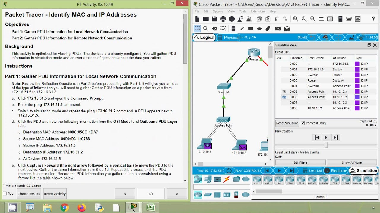
  • 📚 The course includes a lab where network traffic is examined using packet tracer’s 'simulation mode'.
  • 🔍 The network diagram features two routers (R1 and R2), two switches (SW1 and SW2), a server, and a PC, with various interfaces labeled for connectivity.
  • 🌐 G0/0, G0/1, G0/2 interfaces are Gigabit Ethernet, operating at one gigabit per second, while F0/1 is FastEthernet at 100 megabits per second.
  • 🏷️ Network addresses 192.168.1.0/24 and 10.0.0.0/24 are introduced, with subnetting to be explained in upcoming lessons.
  • 📈 The concept of routers connecting different networks is highlighted, with specific IP addresses assigned to devices within the same subnet.
  • 🔬 Packet tracer’s simulation mode is used to visually inspect various types of network traffic, such as STP, OSPF, and DHCP.
  • 🌐 STP (Spanning Tree Protocol) is a Layer 2 protocol, while OSPF (Open Shortest Path First) is a Layer 3 protocol for path discovery.
  • 📚 The OSI model's 7 layers are referenced, with examples of how protocols like STP, OSPF, and DHCP encapsulate data at different layers.
  • 💻 PC1 uses DHCP, a Layer 7 protocol, to automatically obtain an IP address, demonstrated through the release and renewal process.
  • 🔄 The video concludes with a demonstration of how the OSI and TCP/IP models work in a network, with a promise of deeper understanding as the course progresses.

Q & A

  • What is the purpose of the video series provided by Jeremy's IT Lab?

    -The purpose of the video series is to offer a free, complete course for the CCNA 200-301 certification.

  • What are the two types of network interfaces mentioned in the script, and what do their labels indicate?

    -The two types of network interfaces mentioned are Gigabit Ethernet (labeled as 'G') and FastEthernet (labeled as 'F'). The labels indicate the speed of the interfaces, with 'G' operating at one gigabit per second and 'F' at 100 megabits per second.

  • What are the two network addresses mentioned in the script, and what do they represent?

    -The two network addresses are 192.168.1.0/24 and 10.0.0.0/24. They represent the IP address ranges for two separate networks or subnets within the network diagram.

  • What is the significance of the '.100' and '.1' in the IP addresses mentioned for SRV1 and R1's G0/0 interface?

    -The '.100' and '.1' are the host portions of the IP addresses, indicating that SRV1's IP address is 192.168.1.100 and R1's G0/0 interface IP address is 192.168.1.1.

  • What is the role of the Spanning Tree Protocol (STP) in networking?

    -STP is a layer 2 protocol used to prevent loops in a network by creating a loop-free logical topology.

  • How does the script describe the OSI model in relation to STP?

    -The script describes STP as having information in the bottom two layers of the OSI model, indicating that it operates at the Data Link Layer (Layer 2) and the Physical Layer (Layer 1).

  • What is OSPF, and what layer of the OSI model does it operate on?

    -OSPF (Open Shortest Path First) is a layer 3 protocol used to discover the best paths to different networks within an IP network.

  • How does the script illustrate the encapsulation process in networking?

    -The script illustrates the encapsulation process by showing how a device encapsulates a Protocol Data Unit (PDU) into an Ethernet frame at Layer 2 and into a UDP segment at Layer 4.

  • What is DHCP, and why is it used in networking?

    -DHCP (Dynamic Host Configuration Protocol) is a layer 7 protocol used to automatically assign IP addresses and other network configuration parameters to devices on a network.

  • How does the script explain the difference between the OSI model and the TCP/IP model?

    -The script explains that in the TCP/IP model, Layers 5, 6, and 7 of the OSI model are combined into a single layer called the Application Layer, so there is no separate Layer 5 or 6 information.

  • What action does the script suggest taking to support the video series?

    -The script suggests subscribing to the channel, liking the video, leaving a comment, sharing the video, and possibly donating via cryptocurrency, Patreon, or BAT tips through the Brave browser.

Outlines

00:00

🌐 Introduction to CCNA Course and Network Diagram Overview

Jeremy’s IT Lab offers a free, comprehensive CCNA 200-301 course. The video encourages viewers to subscribe, like, comment, and share to support the series. The lab begins with an examination of network traffic using packet tracer's 'simulation mode'. The network diagram features two routers (R1 and R2), two switches (SW1 and SW2), a server, and a PC, with interfaces labeled according to their type and speed. The video explains the difference between gigabit (G) and fastethernet (F) interfaces and introduces the concept of network addresses and subnets. The 192.168.1.0/24 and 10.0.0.0/24 networks are highlighted, with IP addresses for devices within these networks provided. The video promises upcoming lessons on IP addresses and the significance of the /24 notation. The main topic of using packet tracer's simulation mode to analyze network traffic is introduced, with examples of STP and OSPF protocols and their OSI model layer involvement.

05:02

🔍 Deep Dive into OSI and TCP/IP Model Protocols with Packet Tracer

This paragraph delves deeper into the OSI and TCP/IP models by examining network traffic through packet tracer. It starts with an exploration of OSPF, a layer 3 protocol for path discovery, which includes information from all layers down to the physical layer. The video then shifts focus to PC1, which uses DHCP, a layer 7 protocol, to automatically obtain an IP address. The process involves releasing and renewing the IP address, generating DHCP traffic that includes layer 7 information but combines layers 5 and 6 into the application layer as per the TCP/IP model. The video demonstrates accessing the command prompt on PC1, using ipconfig commands to manipulate the IP address, and analyzing the resulting DHCP messages. It concludes with a demonstration of packet tracer's ability to play through network messages, emphasizing that understanding of the OSI and TCP/IP models will improve as the course progresses. The video ends with a call to action for support through subscriptions, likes, comments, and sharing, and mentions the instructor's acceptance of donations and tips via various platforms.

Mindmap

Keywords

💡CCNA 200-301

CCNA 200-301 is a certification exam for Cisco Certified Network Associate, which is a globally recognized certification for networking professionals. The video is part of a free course designed to help viewers prepare for this exam. It is central to the video's theme as it sets the context for the educational content provided.

💡Packet Tracer

Packet Tracer is a network simulation tool used for teaching and learning networking concepts. In the video, it is used to demonstrate network traffic and protocols in action. It is a key tool for visualizing the concepts being taught, allowing viewers to see how data travels across a network.

💡Network Diagram

A network diagram is a visual representation of a network's structure, showing the connections between different devices. In the script, the network diagram includes routers, switches, a server, and a PC, all connected via various interfaces. It is essential for understanding the layout and connectivity of the network being discussed.

💡Gigabit Ethernet

Gigabit Ethernet refers to a transmission speed of one gigabit per second, typically used in network interfaces. In the video, interfaces labeled with 'G' operate at this speed, indicating high-speed data transfer capabilities. It is a key concept for understanding the bandwidth of the network being discussed.

💡Fast Ethernet

Fast Ethernet is a term used for network interfaces that operate at 100 megabits per second, slower than Gigabit Ethernet. In the script, 'F' indicates these interfaces. Understanding Fast Ethernet helps viewers grasp the different speeds at which network devices can operate.

💡Network Address

A network address is an identifier for a network, often in the form of an IP address and a subnet mask. The script mentions '192.168.1.0/24' and '10.0.0.0/24' as examples. These addresses are crucial for identifying the different networks within the diagram and understanding IP addressing.

💡Subnet

A subnet is a smaller network within a larger network, created by partitioning an IP address space. The video mentions a single subnet including several devices, all sharing the same network address. Understanding subnets is important for learning about IP addressing and network segmentation.

💡STP (Spanning Tree Protocol)

STP is a Layer 2 protocol used to prevent loops in a network by creating a loop-free path from the source to the destination. In the video, STP is shown as network traffic originating from SW2. It is a key concept for understanding network redundancy and efficiency.

💡OSPF (Open Shortest Path First)

OSPF is a Layer 3 protocol used for routing and finding the best paths across a network. It is mentioned in the script as a protocol used by R1. OSPF is essential for understanding how routers communicate and determine the most efficient routes for data transmission.

💡DHCP (Dynamic Host Configuration Protocol)

DHCP is a Layer 7 protocol that automatically assigns IP addresses and other network configuration parameters to devices on a network. In the video, PC1 uses DHCP to renew its IP address. Understanding DHCP is important for learning about IP address management in networks.

💡OSI Model

The OSI Model is a seven-layer framework that standardizes the functions of a network system into different layers. The video references this model when discussing protocols like STP and OSPF, which operate at different layers. It is fundamental for understanding how network protocols interact and function within a network.

💡TCP/IP Model

The TCP/IP Model is a four-layer model that is actually used in internetworking, combining some layers from the OSI Model. The video mentions this model in the context of DHCP, which includes information up to Layer 7 but does not differentiate between Layers 5 and 6. Understanding the TCP/IP Model is crucial for grasping how internet protocols are structured.

Highlights

Introduction to a free, complete course for the CCNA 200-301

Encouragement to subscribe, like, comment, and share the video series

Overview of network diagram with routers R1 and R2, switches SW1 and SW2, server, and PC

Explanation of network interfaces and their speeds (Gigabit Ethernet and FastEthernet)

Introduction to network addresses and subnets with examples

Understanding of IP addresses and their notation

Introduction to the OSI model and its layers

Role of the Spanning-Tree Protocol (STP) in network operations

Details on Ethernet Layer 2 header and its components

Physical layer (Layer 1) information and its significance

Introduction to OSPF as a Layer 3 protocol for path discovery

DHCP as a Layer 7 protocol for automatic IP address assignment

Demonstration of how to generate DHCP traffic using packet tracer

Explanation of the TCP/IP model and its relation to the OSI model

Visualization of network traffic and protocol operations in packet tracer

Invitation to support the channel through subscriptions, likes, comments, and shares

Transcripts

play00:01

Welcome to Jeremy’s IT Lab.

play00:03

This is a free, complete course for the CCNA 200-301.

play00:08

If you like these videos, please subscribe to follow along with the series.

play00:12

Also, please like and leave a comment, and share the video to help spread this free series

play00:17

of videos.

play00:19

Thanks for your help.

play00:20

Let’s get started.

play00:22

In this lab we will examine some network traffic using packet tracer’s ‘simulation mode’

play00:27

feature.

play00:28

But first, let’s take a look at the network diagram.

play00:32

There are two routers, R1 and R2, two switches, SW1 and SW2, and one server and one pc.

play00:41

The G0/0, G0/1, G0/2 and F0/1 labels indicate the network interfaces used to connect the

play00:51

devices.

play00:53

G means gigabit ethernet, so these interfaces operate at a speed of one gigabit per second.

play01:00

You migth also see it written as Gi, or Gig, but I usually just use G. F means fastethernet,

play01:09

so these interfaces operate at 100 megabits per second.

play01:14

You might also see it written as Fa, instead of just F. Now these two series of numbers

play01:20

here, 192.168.1.0/24, and 10.0.0.0/24, are the network addresses.

play01:32

Routers are used to connect different networks.

play01:35

There are two networks displayed here in this diagram, the one on the left here includes

play01:39

SRV1, PC1, SW1, SW2, and R1’s G0/0 interface.

play01:47

They are all in a single network, or subnet, a term you will learn about soon.

play01:52

So, that’s the 192.168.1.0/24 network, and the .100 for SRV1 means that its IP address

play02:04

is 192.168.1.100, and the .1 by R1 means that its address is 192.168.1.1.

play02:14

Wait for the lesson about IP addresses coming up soon for more information on this topic.

play02:20

The other network is 10.0.0.0/24, consisting of R1’s G0/1 interface, and R2’s G0/0

play02:27

interface.

play02:28

Notice the .1 and .2, so R1 is 10.0.0.1 and R2 is 10.0.0.2.

play02:40

Hopefully that helps you understand a little bit about how to read a network diagram.

play02:44

Don’t worry if you have no idea how IP addresses work, or what that /24 next to the network

play02:50

addresses means, that will all be explained in a video coming soon.

play02:54

So let’s get started on today’s main topic.

play02:58

I’m going to use packet tracer’s simulation mode, which you can activate here, in the

play03:03

bottom right.

play03:04

Now, I can click through here, and you can see various network traffic being sent around.

play03:10

Let’s take a look at some.

play03:14

At Device SW2 means that SW2 is the one sending out the data.

play03:20

It says type, STP.

play03:22

STP is the spanning-tree protocol, a layer 2 protocol you’ll learn a lot about in this

play03:29

course. Let's click on it, and

play03:32

notice here the 7 layers of the OSI model, and STP has information in the bottom two

play03:38

layers.

play03:39

Let’s look at the Layer 2 header.

play03:43

Notice it says Layer 2: IEEE 802.3 header.

play03:48

You might remember that IEEE 802.3 is the standard number for Ethernet, so this is an

play03:55

Ethernet Layer 2 header.

play03:57

Let’s look at some of the information here.

play04:00

Down here it shows some information about the process, and notice here at number

play04:04

2: the device encapsulates the PDU into an Ethernet frame.

play04:10

There’s the encapsulation process I talked about in the lecture video.

play04:14

Let’s take a look at the Layer 1 info.

play04:18

Notice that the information is the two interfaces that it sends the frame out of.

play04:24

Information like the physical ports, or interfaces, on a device are Layer 1 information, because

play04:29

it is the physical layer.

play04:31

Now let’s look at another bit of network traffic, this time AT device R1, and the type

play04:39

is OSPF.

play04:41

OSPF is a layer 3 protocol, it’s used to discover the best paths to different networks.

play04:49

You’ll learn a lot about it, too, in this course.

play04:53

STP only had Layer 2 and Layer 1 information, but OSPF has Layer 3, Layer 2, and Layer 1

play05:02

information.

play05:03

Notice in the Layer 3 header, source IP address, and destination IP address.

play05:09

Remember, IP addresses are Layer 3 information.

play05:14

Next, to look at some traffic that includes information all the way up to Layer 7, I will

play05:19

go on PC1.

play05:21

Pc1 is using a protocol called DHCP to automatically receive an IP address.

play05:30

To generate some DHCP traffic, and DHCP is a layer 7 protocol, I’ll get PC1 to release

play05:37

its current IP address, and then renew it.

play05:41

When you click on a PC in packet tracer you’ll see this screen.

play05:46

Click on desktop, then command prompt, to access the PC’s command prompt, which functions

play05:51

like a windows command prompt.

play05:54

Type ipconfig, and you can see the current IP address here…...to release the IP address,

play06:02

type ipconfig /release.

play06:05

And now you can see already a DHCP message on PC1.

play06:09

I’ll type the next command to, to renew the IP address.

play06:14

It’s ipconfig /renew.

play06:17

Now let’s check one of these DHCP messages.

play06:22

Notice information all the way up to Layer 7, except layers 5 and 6.

play06:27

That's because in the TCP/IP model, which is the model actually in use, Layers 5, 6,

play06:34

and 7 are all combined into a single layer called the application layer, so you’re

play06:38

not going to see any layer 5 or 6 information, but you can consider it to be part of the

play06:44

layer 7 information.

play06:47

Then there is layer 4 information, if you click on it, it says the device encapsulates the PDU into a UDP

play06:54

segment, remember the Layer 4 PDU is called a segment.

play06:59

Layer 3, Layer 2, and Layer 1 information is present as well.

play07:03

Now, if I just press the play button in the middle, it will slowly play through all of

play07:08

the different messages being sent through the network.

play07:12

That’s all for this lab, I just wanted to show you the OSI and TCP/IP models at work

play07:20

on a network.

play07:22

Your understanding of the functions of these layers might still be a little unclear, but trust me,

play07:27

you’ll understand things better as we start to actually learn about these different protocols

play07:31

that operate at each layer.

play07:36

Thank you for watching.

play07:37

That's all for this video.

play07:39

If you want to show your support, please subscribe to the channel, like the video, leave a comment,

play07:45

and share the video with anyone else studying for the CCNA.

play07:48

I accept donations via cryptocurrency or Patreon via the links in the description.

play07:55

I'm also a Brave verified publisher and accept BAT, or Basic Attention Token, tips via the

play08:00

Brave browser.

play08:02

Click the link in the description to check out ...(video cuts off early)

Rate This

5.0 / 5 (0 votes)

Related Tags
CCNA CourseNetwork TrafficPacket TracerSimulation ModeOSI ModelEthernetIP AddressesSTP ProtocolOSPF ProtocolDHCP ProcessIT Education