How to calibrate RTD temperature transmitters - Beamex
Summary
TLDR本视频由Phoenix BMX和ISA的Michael制作,向观众展示了如何校准RTD温度变送器。首先介绍了两种校准方法,一种是将温度元件连接到变送器并放入加热块中,另一种是通过模拟器模拟电阻变化。视频中详细演示了使用校准器和模拟器进行校准的过程,包括连接测试导线、进行纸面校准、使用通讯器进行传感器调整等步骤。最终,通过精确调整,成功将变送器校准至规格内,并强调了测试设备的准确性和可追溯性的重要性。
Takeaways
- 🔧 校准RTD温度变送器并不困难,有两种主要方法。
- 🌡️ 使用温度元件连接到变送器是常见的校准方法之一。
- 🛁 当无法将探头实际放入温度浴中时,可以通过模拟电阻来校准。
- 📈 通过校准器连接并测量电流,可以观察到4-20mA输出的变化。
- 🔌 四线RTD的连接方式是关键,需要正确连接测试线。
- 📊 使用校准器进行模拟时,可以设置温度范围和校准点。
- 🛠️ 校准过程中可能出现误差,需要通过调整传感器来修正。
- 🔄 进行多点校准时,应确保测试设备准确且可追溯。
- 🔧 使用通讯器进行传感器的精细调整,包括零点和满度调整。
- 📝 校准完成后,应记录校准结果和相关信息。
- 🔄 校准成功后,应断开所有连接并将变送器重新放回系统中。
Q & A
什么是RTD以及它的主要用途是什么?
-RTD是电阻温度检测器(Resistance Temperature Detector)的缩写,主要用于测量温度。它通过检测材料的电阻变化来确定温度,常用于精确温度测量的场合。
在视频中提到的四线RTD是什么意思?
-四线RTD指的是使用四根导线连接的温度传感器,它可以消除导线电阻对测量结果的影响,从而提供更精确的温度读数。
如何将RTD传感器连接到温度变送器?
-将RTD传感器的四根导线分别连接到温度变送器的相应端子上,通常是将两个导线连接到变送器的电源端子,另外两个导线连接到变送器的信号输出端子。
如果不能将RTD传感器实际放入温度校准浴中,有什么替代方案?
-如果不能将RTD传感器放入温度校准浴中,可以使用模拟器来模拟传感器的电阻变化,从而进行校准。
在校准RTD传感器时,为什么不能直接读取0到100摄氏度的范围内的4到20mA输出?
-因为RTD传感器的电阻变化与温度之间的关系是非线性的,所以不能直接将4到20mA输出与0到100摄氏度的温度范围相对应,需要通过校准来建立这种关系。
在校准过程中,如果发现校准失败,应该怎么办?
-如果校准失败,应该检查RTD传感器和温度变送器的连接是否正确,确认使用的校准设备是否准确,并且可能需要重新进行传感器的调整和校准。
如何使用通讯器对RTD传感器进行调整?
-使用通讯器连接到RTD传感器,进入诊断和服务菜单,选择传感器调整选项,按照指示进行两点调整(包括低端和高端),并进行模拟校准信号的输入,以调整传感器的输出。
为什么测试设备需要比被测试单位更精确?
-测试设备需要比被测试单位更精确,以确保测量结果的准确性。通常测试设备的精确度需要是被测试单位的四倍,这样才能检测出被测试单位的误差。
测试设备需要具备哪些特性?
-测试设备需要具备两个关键特性:一是比被测试单位更高的精确度,二是可追溯性,即测试设备需要定期进行校准,以确保其测量结果能够追溯到国家标准。
在校准RTD传感器后,需要做什么来保存校准结果?
-在校准完成后,需要在测试设备上保存校准结果,这通常包括校准的日期、执行校准的人员、校准的参数以及任何相关的校准备注。
完成RTD传感器校准后,下一步应该做什么?
-完成RTD传感器的校准后,应该断开所有连接线,并将传感器重新安装回过程中,确保传感器可以正常工作并提供准确的温度读数。
Outlines
🔧 介绍与RTD校准基础
本段落介绍了Michael从Phoenix BMX和ISA,他制作了一个视频来展示如何校准RTD(电阻温度检测器)温度传感器。他解释了校准RTD传感器的基本方法,包括两种选项:一种是将温度元件连接到传感器并将其放入加热块中进行实际校准;另一种是通过模拟器对传感器进行电阻模拟,从而观察4-20mA输出的变化。Michael还展示了如何使用校准器连接传感器,并测量毫安输出,以及如何将4-20mA输出与0-100摄氏度进行比例转换。
📊 校准过程与故障分析
在这一段中,Michael继续讲解了校准过程,包括使用文档校准器进行无纸化校准。他展示了如何设置校准器,模拟传感器的电阻变化,并进行五个校准点的测试。通过观察校准结果,Michael指出当前的校准失败了,因为误差超过了规定的0.5%的容差范围。他解释了校准失败的原因,并展示了如何使用内置的通讯器对传感器进行调整,以恢复到规格要求。
🔄 完成校准与测试设备的重要性
最后一段中,Michael完成了对RTD传感器的校准,并强调了测试设备的重要性。他提到测试设备需要比被测试单位更精确,并且需要可追溯到国家标准。通过再次校准,他展示了如何确保传感器的输出在容差范围内,并解释了校准过程中的关键点。最后,他总结了如何使用校准器完成RTD温度传感器的校准,并提醒观众在完成校准后断开所有连接,并将传感器重新放回过程中。
Mindmap
Keywords
💡RTD
💡温度变送器
💡校准
💡4-20mA
💡模拟
💡电阻
💡校准器
💡故障标准
💡传感器调整
💡测试设备
💡过程控制
Highlights
介绍了如何校准RTD温度变送器
使用四线RTD和变送器进行校准的基本方法
通过将探头放入加热块中来观察4-20mA输出变化
当无法移除探头时,可以模拟电阻给变送器
演示了如何使用校准器连接并测量变送器
展示了如何将4-20mA输出与0-100摄氏度进行比例换算
解释了如何通过断开探头并连接校准器进行模拟校准
详细说明了四线RTD温度元件的连接方式
介绍了如何使用校准器进行无纸化校准过程
讨论了校准失败的情况和如何通过调整来回到规范
展示了如何使用通讯器进行传感器的两点微调
强调了测试设备需要比被测试单位更精确,并且需要可追溯性
通过校准器模拟RTD并读取4-20mA输出的过程
说明了校准成功后的步骤和如何保存校准结果
提供了如何将校准结果与之前的结果结合的建议
总结了如何完成RTD温度变送器的校准并将其重新放回流程中
感谢观看并鼓励订阅YouTube频道以获取更多类似视频
Transcripts
hi it's Michael from Phoenix BMX and ISA
decided to put together this video to
show you how to calibrate this RTD
temperature transmitter calibrating RTD
transmitted is not that difficult
there are basically two options one is
it looks like this you've got a
temperature element connected to the
transmitter this is not a deep probe
it's a four wire RTD and we've we've got
it connected all we need to do right now
obviously connect our and you know 420
measurement power loop this transmitter
to get it working you would normally put
that probe into the bath into the block
and heat it up and then you will see the
full 220 output changing but sometimes
that's not possible to actually remove
the probe and put it in the bath what
can you do instead well you could
actually simulate the resistance to the
transmitter and therefore you can you
can see the four 220 out changing we're
going to do that later in this video so
I'm going to show you how to do that but
Before we jump there let me just connect
my calibrator to my transmitter so you
can actually see what the full 220
output is so let's go to the calibrator
let's connect and measure milliamps so
I'm going to be supplying 24 volts into
the transmitter and measuring for 220 as
well so let me just do that now okay so
one lead and secondly there right so it
looks as if we've got some live reading
we've got seven point six three seven
point six two milliamps output from that
transmitter so right now if we were to
you know to touch and change you know
the temperature of you put it in D and
you know a bath ice bucket of eyes
anything like that obviously that
temperature would change and milliamps
would change we could actually also see
if we scale that 4 to 20 milliamps
output to zero to 100 Celsius degrees we
can actually have the Celsius degrees as
a scaled value as well so you can see
you can you can do that and if you pod
that again in the in a baffle and if in
like that that would change
so what I'm going to do now is
disconnect this probe from the
transmitter we're going to disconnect
everything we're just going to connect
the leads back to the to the calibrator
and you will see how we can actually do
the calibration using the document and
calibrator and simulating the RTD the
probe is now going to be disconnected
from the transmitter and we are going to
connect our sets of leads and then
subsequently connect this transmitter to
a to a calibrator so this point this is
a four wire and RTD temperature element
so we're going to disconnect that and by
the way whistling here is optional you
don't have to whistle but you can if you
want right
so the MC element is off right now
quickly explained in what can we see
here and this is a normal sort of fall
to 20 RTD and temperature transmitter
you can see right now that the resistor
is is here between 1 & 2 & 3 & 4 so
that's how we're going to connect our
test leads you can see 4 to 20 so this
is where the power lead is going to go
into and this is where we're going to
read the full 20 so let's connect our
test leads
so the red ones going to go to one side
of the register and the black ones going
to go to the other okay all we have to
do right now is obviously we connected
the four wire and for test leads we're
going to connect them into the document
to calibrate it but we also want to
connect right now the power lead so
we're going to do that now so this is
going to provide a loop power to the
transmitter and also going to measure
four to twenty in the same time okay so
we're ready to connect and our test
leads to our calibrator so what we're
going to do is go to our 2d simulation
and we're going to connect the test lead
as shown on this picture
okay so let's see if we simulate zero
what's the 420 output
it seems as if the the output is working
okay so at this stage we could just you
know carry on with the calibration using
our test equipment and what what we're
going to do is go to a document in
calibrator and we want to carry on with
the paperless calibration and we
actually set up one just here and now
which is 0 to 100 4 to 20 on the airport
we've got everything connected or we
have to press right now is start and the
calibrator is going to simulate and the
resistance to the transmitter so it I
can actually you know give us a 420
output and there'll be five calibration
points going up and down you can see the
blue holograms lines these are the
passive failed criteria we set it to
point five of a percent of span and so
it looks as if and all of our points is
going to be outside of that so that's
going to mean a failed calibration but
we'd have to do something about it if we
want to bring it back to spec you can
also see the the red dots this is just
an indication that those points are
outside of our tolerance and you can see
also here that there are the calibration
points and that the calibrate is going
to simulate and four to twenty outputs
going to it's going to be measured okay
so this is our failed calibration it
looks as if we have done 0.75 percent of
span error so this is obviously greater
error than we had dissipated it's 150
percent significant error which means
that we are obviously outside of our
tolerance this value is very important
and because it shows us where we are in
terms of our tolerance and we could put
any information about it wine failed if
we know why it has happened but you can
see the graph you can see the numbers
behind the graph and now we would have
to save this this is our s found
calibration and we could also right now
finish and go and leave it as it is but
we we don't want to leave a failed
calibration so we're going to save it as
found and we're going to right now try
to bring it back
to spec and and to do another
calibration is left
this is a hard transmitter so what we're
going to do is we're going to use our
communicator that it's built in here to
actually communicate and trim the the
sensor and what you could do
alternatively if that's not too hard and
there would be usually a zero and span
screws and you would have to just go
about and try to find and adjust to get
the correct settings but here we're just
going to use our heart communicator so
let me show you how to do that and we
just start the communication so right
now the hard building modem here because
it's going to communicate it to our
transmitter it's going to give us some
options here the tags and and the ranges
but we're not interested in that we
would like to trim that transmitter so
you're going to go to diagnostic and
service we're going to go to sensor
Trinh and we're going to go to two-point
trim we recommend doing two-point trim
and because you want to do a lower and
the upper trim and we also going to do
the analog trim in there is going to be
graphic shown here somewhere so you can
just have a look at why we doing both
but they are in Syria so we have to do
both okay we just following the
instructions as they are displayed here
on the screen you just click OK and
click - another instruction you can see
right now they're at the moment at zero
it's it's built just below zero so we've
got to copy this value into this cell by
just clicking that number one there and
you click OK and it's asking us to apply
the hi and the value right now we know
the high value was hundred so we're
going to do that and again synod's
stable you click OK if you follow the
instruction you click OK again and again
you copy information from box number one
into into the sensor and you can see
right now how milliamps quickly trimmed
so it looks as if we are onto something
good here so let's just come up and
let's just do the animal trim as well
again we follow the instructions set by
our and my Oh didi files entered it in
that it's inside the transmitter okay
set the transmitter to 4 milliamps we
again copy the value we agreeing that
we've seen four milliamps and we
following the instructions as we were
before you copy the value from box
number two into it it click OK and yes I
can see 20 milliamps it looks as if we
trimmed and both digital and analog
let's go back to our test and we're
ready to do the s left calibration now
let me just check at 100 we seem around
20 milliamps it's okay what happens if I
go to the lower end you can see we had
zero reading out 4 milliamps we happy
with that so let's hit start so you can
see right now the transmitter is going
to simulate the RTD into and into it and
it's going to read the 420 out you can
see steps is going to go five step up
five step down you can see the step size
here and this actually is a very good
time to talk about calibrators itself
the test equipment what does it make
what does make test equipment test
equipment it two things one it needs to
be more accurate probably four times
more accurate than the unit on the test
that's one thing second thing it needs
to be traceable it needs to be in date
so it needs to be traceable to national
standard so we need to send it to
calibrations lab for traceability and
those two things are out of critical and
most important when we actually talking
about test equipment we need to always
bear that in mind you can see our
calibration is on the way
it slowly goes through those five point
up and five point down you can see next
point is 50 it waits eight second
actually to get this stable reading and
then it and sort of capture that value
there and then
okay so it looks as if we are well in
tolerance as opposed to previously when
we were 150% significant error out we
only 20% significant error right now so
we reduced up massively you can see it's
a passed calibration we we obviously
trimmed it that's why we we got there
you can see we can put information about
who did the calibration and any
calibration notes you can see the graph
so you can you can pretty much share say
here that we are well within tolerance
so that's all good we can save this
calibration we can actually do save this
calibration there's left we can also
combine this with the previous results
if that was the case and we can just
save it and there you have it that's how
to calibrate RTD transmitter using the
calibrator document in calibrator we've
just completed calibrating this RTD
temperature transmitter all we have to
do right now is disconnect all the
cables and put it back into the process
so I have to connect back to pro thank
you so much for watching and for more
videos like this please see our youtube
channel
Browse More Related Video
![](https://i.ytimg.com/vi/gomyUdHfi1U/hq720.jpg)
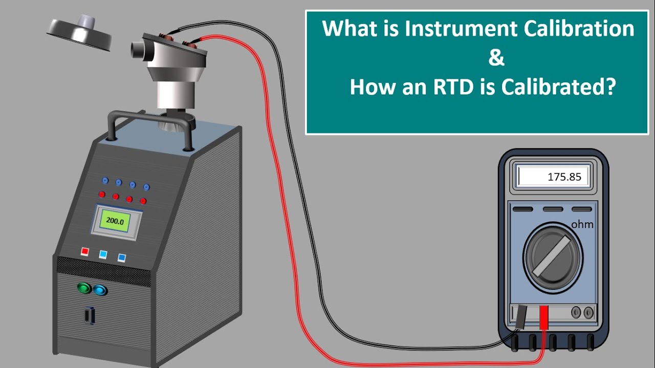
what Is Instrument Calibration. Instrument Calibrator. RTD Calibration. Calibration certificates.
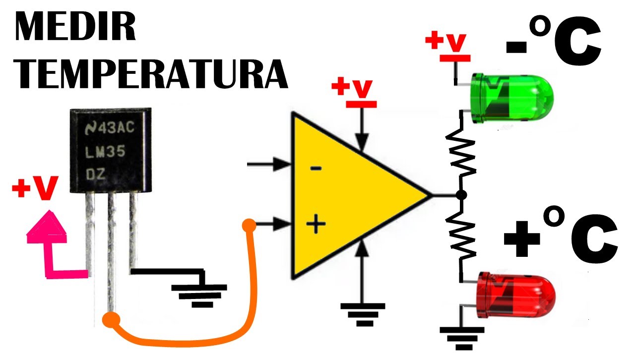
![](https://i.ytimg.com/vi/5-NGbSVSUJc/hq720.jpg)
RTD in detail tutorial explaining 2 Wire RTD , 3 Wire RTD and 4 Wire RTD
![](https://i.ytimg.com/vi/n_lZCIA25aI/hq720.jpg)
What is Sensor Calibration and Why is it Important?
![](https://i.ytimg.com/vi/Qj_qfSrBnAg/hq720.jpg?sqp=-oaymwEmCIAKENAF8quKqQMa8AEB-AH-CYAClgWKAgwIABABGEsgWShlMA8=&rs=AOn4CLAD07FXfhwdsZ_7p8BpUec5ZZJHOA)
Model Predictive Control of Boost Converter
![](https://i.ytimg.com/vi/DkcHiZS_zR8/hq720.jpg)
Zhiyun Molus X60 - Long Term Review
![](https://i.ytimg.com/vi/e2U0x4HrQb8/hq720.jpg)
🔶Mejora Tu SEÑAL RSSI en Tu DRON FPV🔶Prueba y Comparativa Modulo Externo | Super G Nano, BetaFPV
5.0 / 5 (0 votes)