RTD in detail tutorial explaining 2 Wire RTD , 3 Wire RTD and 4 Wire RTD
Summary
TLDR本期视频由calibration Academy频道带来,主题是电阻温度探测器(RTD)。视频将讲解RTD中的引线电阻是什么,为何三线RTD比二线RTD更准确,以及四线RTD如何更胜一筹。最后,将展示如何将RTD连接到温度变送器。通过Wheatstone桥式电路分析引线电阻对测量误差的影响,并解释三线和四线RTD如何减少这种误差。四线RTD通过电压信号而非电阻来测量温度,提供更高精度。视频还介绍了四线RTD的优点和缺点,并指导如何将不同线型的RTD连接到温度变送器。
Takeaways
- 🔍 视频介绍了电阻温度探测器(RTD)的相关知识。
- 🔌 讲解了二线RTD中的引线电阻及其对测量误差的影响。
- 📉 引线电阻会随着RTD和温度变送器之间距离的增加而增加测量误差。
- 🌡️ 通过惠斯通电桥原理解释了二线RTD的工作原理和误差产生。
- 📈 通过实例演示了正确测量和引线电阻导致的测量误差。
- 🔌 三线RTD通过额外的引线消除了电路中的有效引线电阻,比二线RTD更常用于工业中。
- 🔄 三线RTD通过惠斯通电桥方程,使得引线电阻在电路中相互抵消,提高了准确性。
- 🔌 四线RTD基于电压信号而非电阻测量温度,因此比二线和三线RTD更准确。
- 💡 四线RTD的优点包括更高的准确性和不受引线电阻影响,常用于需要精确温度读数的实验室。
- 🔋 四线RTD的缺点包括成本较高和长时间使用可能因自热产生小量测量误差。
- 🔧 视频还展示了如何将二线、三线和四线RTD连接到温度变送器。
Q & A
什么是RTD的引线电阻?
-引线电阻是指在实际应用中,连接RTD和温度变送器的电缆本身所具有的电阻,这部分电阻会加到RTD的电阻上,从而引入测量误差。
为什么三线RTD比二线RTD更准确?
-三线RTD通过使用额外的引线来消除电路中的有效引线电阻,这样可以避免二线RTD中因引线电阻而产生的测量误差。
四线RTD为什么比二线和三线RTD更准确?
-四线RTD基于电压信号而非电阻来测量温度,通过测量通过RTD的恒定电流和电压降来确定温度,因此不受引线电阻的影响。
如何将RTD连接到温度变送器?
-根据RTD的线数,将相应的电缆连接到温度变送器的指定端子上,二线RTD连接到端子4和5,三线RTD连接到端子4、5和6,四线RTD连接到端子3、4、5和6。
为什么测量误差会随着RTD和温度变送器之间距离的增加而增加?
-因为引线电阻会随着电缆长度的增加而增加,这会导致测量误差的增加。
在惠斯通电桥中,RTD的电阻是如何影响测量的?
-在惠斯通电桥中,RTD的电阻与引线电阻一起被测量,如果电桥不平衡,就需要考虑引线电阻对测量结果的影响。
为什么在三线RTD中需要使用等长的引线?
-使用等长的引线可以确保两边的引线电阻相互抵消,避免因引线电阻不同而引入额外的测量误差。
四线RTD的优点是什么?
-四线RTD的优点包括更高的测量精度,不受引线电阻影响,适用于需要精确温度读数的实验室环境。
四线RTD的缺点有哪些?
-四线RTD的缺点包括成本较高,长期使用可能会因为自热效应而产生小量的测量误差。
如何避免在四线RTD中因自热效应而产生的测量误差?
-通过优化温度变送器的设计,减少电流通过时产生的热量,可以降低自热效应对测量结果的影响。
Outlines

This section is available to paid users only. Please upgrade to access this part.
Upgrade NowMindmap

This section is available to paid users only. Please upgrade to access this part.
Upgrade NowKeywords

This section is available to paid users only. Please upgrade to access this part.
Upgrade NowHighlights

This section is available to paid users only. Please upgrade to access this part.
Upgrade NowTranscripts

This section is available to paid users only. Please upgrade to access this part.
Upgrade NowBrowse More Related Video
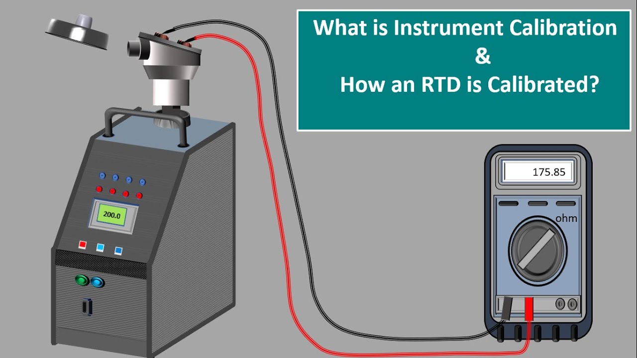
what Is Instrument Calibration. Instrument Calibrator. RTD Calibration. Calibration certificates.
EMC tutorials - [1/3] Building an LISN
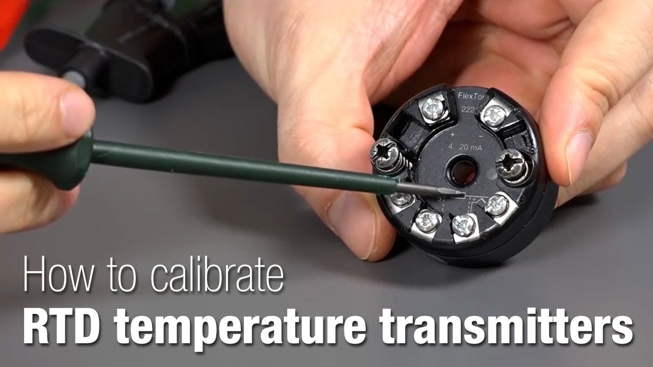
How to calibrate RTD temperature transmitters - Beamex

客户开发 | 外贸客户开发之主动开发,只需四步,从此不再缺订单 | 国际贸易

I Demo a 12 String Acoustic Electric Guitar That's Under $200 - How Good Can It Actually Be?

Dynaudio Focus 30 vs. Evoke 30 + Hegel H190 | Aktiv vs. Passiv Lautsprecher Vergleich!
5.0 / 5 (0 votes)
