Fusion 360 beginner's Exercise #1 - Fusion 360 tutorial
Summary
TLDRThis video tutorial demonstrates how to create a 3D 90-degree elbow joint for pipelines using Fusion 360, focusing on enhancing design skills. The presenter walks through steps to design the elbow joint, including drawing arcs, lines, and setting pipe thickness and dimensions, followed by creating extrusions and holes for accuracy. It also covers adding finishing touches like fillets and appearances. The video is targeted at beginners to Fusion 360 and encourages viewers to subscribe and support the channel via PayPal.
Takeaways
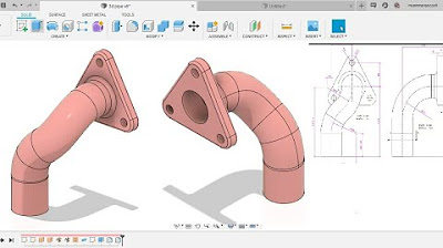
- 🔧 The video tutorial focuses on creating a 3D 90-degree elbow used to join pipelines in Fusion 360.
- 🎯 This tutorial is aimed at improving viewers' design skills in Fusion 360, specifically for creating 3D models.
- 🚀 Beginners to Fusion 360 are encouraged to subscribe to the channel for more tutorials.
- 💡 The 90-degree elbow is constructed by starting with a center circle and creating an arc with a radius of 200 mm and a diameter of 400 mm.
- ✂️ Excess parts of the circle are trimmed to shape the arc, followed by drawing horizontal and vertical lines to complete the form.
- 🔩 The pipe's hollow section is created by specifying dimensions such as an outer diameter of 100 mm and an inner diameter of 75 mm.
- 📏 The extruded part has a diameter of 150 mm and is extruded by 20 mm on both sides of the elbow.
- 🌀 Circular patterns are used to create holes in the design, with a diameter of 10 mm for each hole and positioned 65 mm from the center.
- 🎨 The video also covers adding appearance options like polished copper to enhance the look of the final model.
- 📢 The creator encourages viewers to like, comment, share, and support the channel financially via PayPal.
Q & A
What is the main focus of the video tutorial?
-The main focus of the video tutorial is to guide viewers on how to create a 3D 90-degree elbow joint for pipelines using Fusion 360 software.
What is the purpose of the 3D 90-degree elbow shown in the video?
-The 3D 90-degree elbow is used to join pipelines that meet at a 90-degree angle.
What are the assumed dimensions for the pipe in the tutorial?
-The assumed dimensions for the pipe are 100mm for the thickness and 200mm for the radius of the arc at which the pipe bends.
How does the tutorial instruct to create the arc for the elbow joint?
-The tutorial instructs to create the arc by drawing a circle with a diameter of 400mm, then using the trim command to create the desired arc with a radius of 200mm.
What are the steps to ensure the lines are tangent to the arc in Fusion 360?
-The tutorial demonstrates using the 'tangent' option in Fusion 360 to ensure the lines are tangent to the circle after drawing the horizontal and vertical lines for the elbow joint.
How is the pipe section created in the tutorial?
-The pipe section is created by using the 'Pipe' command in Fusion 360, selecting the path, and specifying the section size and thickness.
What is the outer diameter and thickness of the pipe used in the tutorial?
-The outer diameter of the pipe is 100mm, and the thickness is 12.5mm, which is calculated by dividing the difference between the outer diameter and the inner diameter by 2.
How are the extruded parts created after the pipe section in the tutorial?
-The extruded parts are created by drawing circles with a diameter of 150mm and using the 'Extrude' command to extrude them to 220mm.
What is the process to create the holes in the elbow joint as described in the tutorial?
-The holes are created by drawing a circle with a diameter of 10mm, setting the distance from the center to 65mm, and then using the 'Extrude' command to create the holes. A 'Circular Pattern' feature is then used to create 6 holes around the circle.
How does the tutorial modify the fillet radius of the elbow joint?
-The tutorial modifies the fillet radius by using the 'Fillet' command, selecting the edge of the elbow joint, and specifying a radius of 5mm.
What is the final step to enhance the appearance of the 3D model in the tutorial?
-The final step to enhance the appearance of the 3D model is to apply a 'Copper' or 'Bronze' appearance to give the pipe a polished look.
Outlines

このセクションは有料ユーザー限定です。 アクセスするには、アップグレードをお願いします。
今すぐアップグレードMindmap

このセクションは有料ユーザー限定です。 アクセスするには、アップグレードをお願いします。
今すぐアップグレードKeywords

このセクションは有料ユーザー限定です。 アクセスするには、アップグレードをお願いします。
今すぐアップグレードHighlights

このセクションは有料ユーザー限定です。 アクセスするには、アップグレードをお願いします。
今すぐアップグレードTranscripts

このセクションは有料ユーザー限定です。 アクセスするには、アップグレードをお願いします。
今すぐアップグレード関連動画をさらに表示
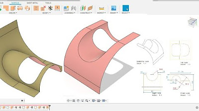
Fusion 360 beginner's Exercise #9 - Fusion 360 tutorial
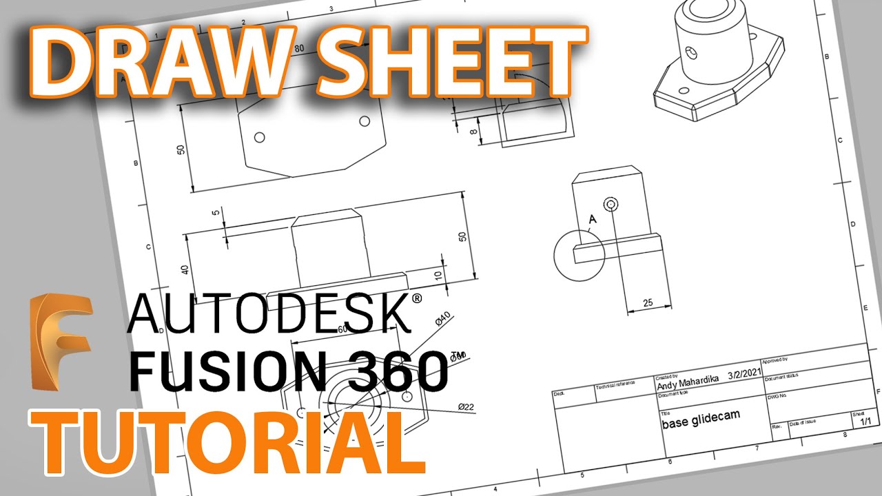
Fusion 360 Tutorial : Membuat Gambar kerja - Untuk pemula
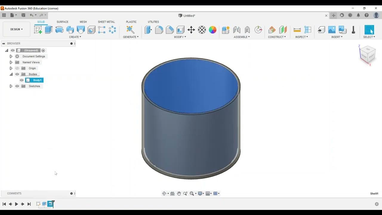
Part Modeling - Create a Shell Feature
Fusion 360 beginner's Exercise #10 - Fusion 360 tutorial
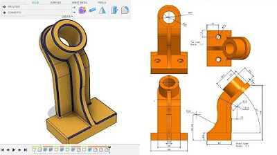
Fusion 360 beginner's Exercise #8 - Fusion 360 tutorial

How to make 3D Printed LED signs - easier & cheaper tutorial
5.0 / 5 (0 votes)
