Fusion 360 beginner's Exercise #8 - Fusion 360 tutorial

SPARK PLUG
28 Nov 201914:32

Summary

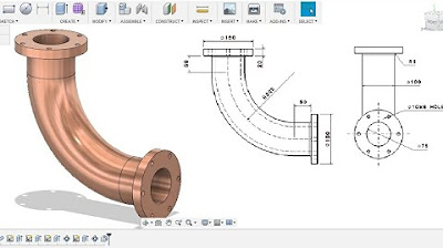
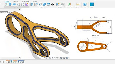
TLDRIn this tutorial, the host demonstrates the process of creating a hose pipe in Fusion 360, a 3D CAD software. Starting with a sketch of the pipe's profile on the front and side views, the tutorial guides through combining these sketches to form a 3D model. It covers steps like extruding the profile, trimming excess parts, and using the 'Pipe' command to create a hollow pipe with specified outer diameter and thickness. The video concludes with adding a mounting profile and emphasizes the importance of accuracy and precision in the design process.

Takeaways

  • 🔧 The video is a tutorial on creating a hose pipe in Fusion 360, a 3D CAD software.
  • 📈 The tutorial provides a downloadable EDL drawing file for reference, available in the video description.
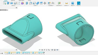
  • 📝 The main challenge is modeling the hose pipe across three axes simultaneously, involving a snake-like profile.
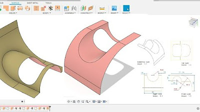
  • 📐 The process begins with sketching the profile on the front view, involving straight lines, arcs, and circles with specific dimensions.
  • 📉 After the front view sketch, the same is replicated on the side view, focusing on the L-shaped profile with a 70mm radius at the center.
  • 🔄 The two sketches are combined to create a 3D sketch, using the 'Form' command in Fusion 360.
  • 📊 The outer diameter of the pipe is set to 52mm, with an inner diameter of 50mm for the sweep operation.
  • 🛠️ The tutorial demonstrates how to use extrude and trim commands to shape the pipe's body and handle mounting details.
  • 🔄 The 'Pipe' command is used to create the hollow section of the pipe with a specified outer diameter, thickness, and using a circular profile.
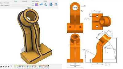
  • 🔄 Additional sketches are made on the pipe's surface to create the mounting profile, involving circles and lines with tangent relationships.
  • 🎉 The final step includes creating a circular pattern of the mounting profile and extruding it to complete the hose pipe design.

Q & A

  • What is the main topic of the video tutorial?

    -The main topic of the video tutorial is to demonstrate how to create a hose pipe in Fusion 360 using a provided tool EDL drawing.

  • Where can viewers find the downloadable file for the tool EDL drawing mentioned in the video?

    -Viewers can find the downloadable file for the tool EDL drawing in the description below the video.

  • What is the outer diameter of the hose pipe that the tutorial is focusing on?

    -The outer diameter of the hose pipe being discussed in the tutorial is 52mm.

  • What is the first step in creating the hose pipe sketch on the front view?

    -The first step in creating the hose pipe sketch on the front view is to draw a horizontal line with a dimension of 50mm.

  • What is the radius of the first arc drawn in the sketch?

    -The radius of the first arc drawn in the sketch is 60mm.

  • How is the second arc in the sketch different from the first arc?

    -The second arc has a different position and a vertical distance of 10mm from the previous point, and it is tangent to the first arc.

  • What is the purpose of the trim command used in the tutorial?

    -The trim command is used to remove the excess part of the sketch that is not required for the final design of the hose pipe.

  • What is the method used to combine the front and side view sketches into a 3D sketch?

    -The method used to combine the front and side view sketches into a 3D sketch involves extruding the sketches and then using the trim command to refine the shape.

  • What is the section size and thickness specified for the hose pipe in the tutorial?

    -The section size for the hose pipe is 50mm with an outer diameter of 50mm and a thickness of 3mm.

  • How many circles are used to create the profile on the face of the hose pipe in the tutorial?

    -Two circles are used to create the profile on the face of the hose pipe, with one having a radius of 50mm and the other two smaller ones having a radius of 12mm each.

  • What is the final step in completing the hose pipe design after creating the profile?

    -The final step is to extrude the profile with a distance of 15mm and then fillet the edges with a 10mm radius to complete the hose pipe design.

Outlines

00:00

🛠️ Designing a Hose Pipe in Fusion 360

This paragraph introduces a tutorial video on creating a hose pipe design in Fusion 360. The host provides a downloadable tool EDL drawing for viewers to follow along. The video will demonstrate how to sketch the pipe's profile on the front and side views, and then combine these sketches to form a 3D model. The host outlines the process of creating a snake-like profile, including dimensions for the outer diameter and mounting details. The tutorial begins with sketching a straight line and an arc on the front view, using specific measurements to ensure accuracy.

05:02

🔄 Sketching and Extruding the Hose Pipe Profile

The second paragraph continues the tutorial by detailing the steps to create the hose pipe's profile on the side view, which includes an 'L' shape with a 70 mm radius. The host explains how to use the 'Combine' command in Fusion 360 to merge the front and side views into a 3D sketch. The process involves extruding the sketches to create the pipe's body and then using the 'Trim' command to refine the shape. The host also discusses the importance of maintaining symmetry and the correct dimensions for the pipe's outer diameter and thickness.

10:02

🔩 Finalizing the Hose Pipe Design with Fusion 360

The final paragraph concludes the tutorial by guiding viewers through the final steps of the hose pipe design. This includes adjusting the length of the pipe to 100 mm, creating a circular section for the pipe's profile with a specified outer diameter and thickness, and using the 'Pipe' command to generate the final 3D model. The host also demonstrates how to create a pattern of circles on the pipe's surface and extrude them to add thickness. The video ends with a review of the completed design and a call to action for viewers to share suggestions for future videos and to subscribe to the channel.

Mindmap

Keywords

💡Spark Plug

A spark plug is a device used in internal combustion engines to ignite the air-fuel mixture by generating an electric spark. In the context of the video, it seems to be a metaphorical reference to the tutorial's subject, suggesting that the video will provide a spark of knowledge or ignite understanding about creating a hose pipe in Fusion 360.

💡Fusion 360

Fusion 360 is a 3D CAD, CAM, and CAE software platform developed by Autodesk. It is widely used for creating and modifying 3D models, which is the core focus of the video. The script mentions using Fusion 360 to design a hose pipe, indicating that the software is central to the video's theme of design and modeling.

💡Hose Pipe

A hose pipe is a flexible tube used to transport fluids or gases. In the video, the hose pipe is the main subject of the tutorial, with the script detailing the steps to model it in Fusion 360, thus making it a key concept for understanding the video's content.

💡Sketch

In the context of CAD software like Fusion 360, a sketch is a 2D drawing used as a basis for creating 3D models. The script mentions creating sketches on the front and side views, which are essential steps in designing the hose pipe, highlighting the importance of sketching in the modeling process.

💡Profile

A profile in CAD design refers to a side view or outline of an object. The video script describes creating a 'snake-like profile' on the front view and a corresponding profile on the side view, which are then combined to form a 3D sketch of the hose pipe.

💡Extrude

Extrusion in 3D modeling is the process of creating a 3D object from a 2D profile by pushing it along a path or distance. The script describes extruding sketches to form the body of the hose pipe, a fundamental operation in the tutorial.

💡Trim

Trimming in CAD involves removing excess material from a 3D model to refine its shape. The video script mentions using the trim command to remove parts of the extruded sketches to achieve the desired shape of the hose pipe.

💡Sweep

Sweep in 3D modeling is similar to extrude but involves a profile moving along a path that is not straight, creating complex shapes. The script refers to sweeping a circular profile to form the pipe, which is a key step in the tutorial.

💡Section Size

Section size in the context of the video refers to the dimensions of the cross-section of the hose pipe, including its outer diameter and thickness. The script specifies the section size as part of the process to create the pipe, emphasizing the importance of these measurements in the design.

💡Circular Pattern

A circular pattern in CAD is a feature that duplicates an object evenly around a circle. The script describes creating a circular pattern of circles on the hose pipe's surface, which is a step in adding detail to the model.

💡Tangent

In geometry and CAD, a tangent is a line or surface that touches another at a single point without crossing it. The script mentions creating tangent relationships between arcs and lines in the sketches, which is crucial for ensuring smooth transitions in the hose pipe's design.

Highlights

Introduction to the tutorial on creating a hose pipe in Fusion 360 with a downloadable tool EDL drawing.

Explanation of the hose pipe's design complexity, particularly the triangular mounting.

Demonstration of sketching the hose pipe's snake-like profile on the front view.

Instructions on creating a straight line and arc for the hose pipe's profile with specific dimensions.

Use of the 'Create Sketch' tool to draw a horizontal line with a dimension of 50 mm.

Creation of arcs with a radius of 60 mm and specific distances from the horizontal line.

Technique of using tangent constraints to connect the arcs and lines in the sketch.

Trimming excess parts of the sketch to finalize the hose pipe's profile.

Transition to creating the side view sketch of the hose pipe with an 'L' shaped profile.

Combining the front and side view sketches to create a 3D sketch in Fusion 360.

Extrusion of the sketch to create the initial shape of the hose pipe with a 50 mm diameter.

Use of the 'Trim' command to refine the shape by trimming the first extrusion with the second.

Miscalculation correction by adjusting the extrusion length to 100 mm for accuracy.

Utilization of the 'Pipe' command to create the hose pipe with a specified section size and thickness.

Creation of a profile on the hose pipe's face with two circles of different radii.

Application of the 'Circular Pattern' tool to replicate the circles around the hose pipe's circumference.

Finalizing the hose pipe design by extruding the profile to add thickness and using the 'Fillet' command.

Completion of the hose pipe tutorial in Fusion 360 with a summary of the process.

Invitation for feedback and suggestions for future video content, along with a call to action for sharing and subscribing.

Transcripts

play00:00

[Music]

play00:15

hey guys and welcome back to another

play00:17

video of a spark plug so in this video

play00:19

tutorial I am going to show you how to

play00:20

make this hose pipe in fusion 360 and

play00:24

here's the tool EDL to be drawing of it

play00:26

you guys can find the downloadable link

play00:29

to this file in the description below so

play00:31

don't forget to check it out

play00:33

so here it is are being brought up front

play00:35

view and a side view and some cut

play00:38

section which represent the overall

play00:39

thickness of the pipe and the outer die

play00:41

of the pipe and the cut section here

play00:43

which represents that either of the

play00:45

mounting on which this pipe is supposed

play00:48

to be mounted so basically the pretty

play00:50

part is not be that this triangular

play00:53

mounting the tricky part is to make this

play00:56

pipe in all across three axes at once so

play00:59

basically what I'm going to do is I am

play01:01

going to sketch this this snake-like

play01:03

profile or repressive presenting on the

play01:07

front view and then I am going to make

play01:11

the same thing on the side view and then

play01:14

I am going to make a combination of

play01:17

these two sketch which will further we

play01:19

use to make us wave off suppose that

play01:22

outer diameter is 52 we are going to

play01:24

make a sweep on that profile so diameter

play01:26

would be off 50mm and then we will deal

play01:30

with the thickness kind of and this

play01:31

mounting kind of stuff

play01:33

so what what I am going to do is I'm

play01:34

going to make this profile on front view

play01:37

we will start by making a straight line

play01:40

upward distance of it 50 at represent

play01:42

here then at our kinnear another arc and

play01:44

then on straight line up to this point

play01:47

this is the center of the hold so what I

play01:50

am going to do is go back to the new

play01:54

design click on create a sketch and on

play01:58

the weary front plane start making your

play02:01

sketch press elf online and draw a

play02:04

horizontal line of 50 mm dimension you

play02:09

can give it to a dimension of 50 mm and

play02:12

press Enter

play02:13

now the next step is to make this arc

play02:17

the radius of this arc is 60 and the

play02:20

distance is 50 from the horizontal

play02:22

and vertically is distance is 60 mm what

play02:25

I am going to do it I am going to create

play02:27

a circle of daya 120 mm which represents

play02:32

radius of 60 mm as mentioned here and

play02:35

the distance from the bottom of this

play02:37

point is 50 and here's what a key is 16

play02:40

so I am what I am going to do is shift

play02:44

it like this this T 4 dimension and from

play02:48

origin given it a dimension of 50 mm and

play02:52

from this gave it a dimensional steel

play02:56

Emin like this now I am going to make

play03:01

the another arc like this of area 60

play03:04

this time the distance would be ones

play03:06

forty seven point five from the bottom

play03:07

and towards the left vertical distance

play03:10

would be 10 mm so again press C for

play03:13

circle again draw a circle of 120 gaya

play03:16

and press enter press D and give it a

play03:20

dimension from the bottom of one forty

play03:23

seven point five and press Enter and

play03:27

vertically this distance from that point

play03:30

would be ten like this so once did

play03:35

once done the only thing left is to make

play03:39

this particular line as you can still

play03:42

see the center distance from this point

play03:44

to the bottom is given 150 mm so what

play03:48

I'm going to do and of course a distance

play03:50

lambda a distance of this line from this

play03:54

line is given it's 50 here what I am

play03:56

going to do is press a line and draw a

play03:59

line like this and press d for dimension

play04:02

select this line and the first line you

play04:06

have drawn and give it a dimension of as

play04:08

you can see the dimension is 50 mm so

play04:13

they belittle dimension of 50 mm and

play04:17

press enter now the top point from this

play04:22

very point is going to be this given the

play04:26

center point of the circle from the

play04:27

bottom is 150 so I am going to make this

play04:30

as

play04:31

150 and press Enter

play04:35

you spread it down so here is the line

play04:38

just drag it down because we don't mean

play04:40

here it here now what you have to do is

play04:43

as due to some in due to some mistakes

play04:51

in measurements in micron levels we used

play04:54

to make Indian constraint between these

play04:57

components so for that what I have to do

play04:59

is what I'm going to do is suppose just

play05:01

delete that 64 now and give the tangent

play05:05

relation between this circle and this

play05:07

light and other click on this circle and

play05:11

this circle but before that delete this

play05:15

tangent line

play05:17

delete this 10mm and press enter and

play05:20

again click on this circle and this

play05:22

circle and maintain in relation again

play05:25

delegate this 50 mm dimension also and

play05:27

give the dimension our tangent

play05:29

relationship between this line and this

play05:31

line once done press T for trim delete

play05:35

these this excess part which we don't

play05:39

require like this a very small part of

play05:42

that line that we have drawn will be

play05:45

left here and press ENTER once turn now

play05:48

all we left is this go with finish the

play05:52

sketch for now click connect symmetric

play05:54

view now once completely completed with

play05:57

the sketch we are going to make the meet

play06:00

this sketch on the side view so for that

play06:02

you go to create a sketch and take the

play06:05

side plane now yet here's the sketch so

play06:13

now what I'm going to do is I'm going to

play06:16

make this dotted line dotted part so as

play06:19

you guys can see basically this is

play06:23

actually a l with the radius of 70 mm at

play06:26

the center so I am going to make this L

play06:27

from the very bottom point up to a

play06:29

distance of 150 and a distance from here

play06:32

to here is hindered mm so press L for

play06:36

line from this point to this point and

play06:40

here's the L so this

play06:43

is from this point to this point a

play06:46

dimension would be 150 this line would

play06:52

be off hundred mm yeah hundred mm and

play06:56

this 150 and the radius is ah are 70 so

play07:02

press fill it so let this line this line

play07:05

and give me the radius of 70 mm bring

play07:09

back the earliest which we have drawn

play07:10

and click on finish the sketch now once

play07:14

turn what I am going to do is I am going

play07:16

to combine these two is sketch to make

play07:19

our 3d sketch so contact if yes if you

play07:22

are familiar with the book space of

play07:24

solid also cat-eared is a command called

play07:26

for my sketch which basically combines a

play07:29

2-dimensional sketch and creates a

play07:31

three-dimensional respect with respect

play07:34

to that but in future if we don't have

play07:36

such options who I am going to do is and

play07:38

this is basically my way of doing things

play07:40

they might they might be some another

play07:41

good ways so please comment in the

play07:43

comment section below if you are if you

play07:45

are having any good at half ways so what

play07:48

I'm going to do for now the switch

play07:50

switch off the first sketch go to create

play07:53

extrude and extrude the second sketch we

play07:57

have drawn and distance would be

play08:01

symmetric so it will be a new body

play08:06

dimension 50mm would be okay

play08:08

and press okay now bring that the first

play08:11

sketch and click on stool extrude this

play08:16

line and this time a symmetric the

play08:19

distance would be symmetric and the

play08:21

total distance one sided distance would

play08:24

be hundred mm the reason why I am making

play08:29

this hundred mm because if we just look

play08:32

closely the distance from this warm

play08:35

point towards this part to the outer

play08:37

outer most point is hindered mm that's

play08:40

why I am taking this extrude up to a

play08:41

distance of hundred mm so that it don't

play08:44

get away from this point so once done

play08:47

what I'm going to do is I'm going to

play08:51

click on the trim command I'm going

play08:54

to now select the trim command and

play08:58

select the second extrusion of hundred

play09:01

mm both side which you have drawn and

play09:03

then select on the first X tool in which

play09:05

you have made and press ok

play09:07

what it will do it will trim the first

play09:10

extrusion with respect to the second

play09:12

extrusion so let's just hide the second

play09:14

extrusion and here we are here's what we

play09:19

got here is with us now again go to

play09:21

solid and now we are going to leave the

play09:24

pipe UV I have their adoption this

play09:27

another option you can actually sweep

play09:29

the circular profile the simplest way is

play09:32

to make the file what it will ask you

play09:34

about the path so don't forget to

play09:36

uncheck the change selection select on

play09:39

this point this select all these lines

play09:44

of fluid is up to

play09:53

okay one thing I have done wrong so just

play09:55

cancel this for now now what you have to

play09:59

do is just go to the first extrusion

play10:02

remember the first extrusion we have

play10:04

fraud and just increase the length we

play10:06

have actually made this 50 mm but I have

play10:09

to make this 100 mm also like this and

play10:13

press ok now you can see now we have our

play10:16

complete sketch here basically I have

play10:18

miscalculated that 50 mm there so what I

play10:21

now go to create go to pipe and select

play10:25

and select the gene select all these

play10:29

lines like I am doing here very end like

play10:36

this

play10:37

so now it will ask you about the section

play10:41

size that section will be circular and

play10:43

the section size the section size is

play10:45

given here the cut section at 8 outer

play10:48

dies 50 and thickness is 3 so what I'm

play10:51

going to do is the section size would be

play10:53

50 and we'll select the hollow section

play10:56

and the section thickness would be 3 and

play10:59

this is going to be our new component

play11:02

and press ok and turn now we can switch

play11:06

off the the spaces body now we are going

play11:11

to make this profile on this very face

play11:13

so for that we need to draw these two

play11:16

circles like here so for that click on

play11:19

create a sketch select on this print

play11:22

plane and draw a circle from this very

play11:25

center of 50 mm as it gets can see the

play11:29

inner radius radius of this circle is 22

play11:32

so the Daiya the outside Dyer would be

play11:38

of 44 so for that just give it a

play11:44

dimension of 44 and press Enter

play11:50

now next thing is to make these three

play11:54

circles or distance from the center

play11:56

point is 50 and the radius is of the

play11:58

screen so for that up to a vertical

play12:01

point draw radius of 20 mm diameter no

play12:07

actually that I radius is given here I

play12:11

have took the outer one so the inner

play12:14

would be having radius of 6 that means

play12:17

12 so another make circle of radius 12

play12:21

diet 12 and from here to here give it a

play12:25

dimension of 50mm now go to create go to

play12:31

circular pattern objects would be the

play12:34

big circle and the smaller one and the

play12:36

center point is going to be this the

play12:38

quantity would be 3 and place ok now

play12:41

click on this first point right click

play12:43

and click no it's a cute pic so we don't

play12:47

have to make anything again press L for

play12:51

line and join all this point like this

play12:59

now all we need to get do is give the

play13:02

tangent relationship between them and

play13:06

this is already changing now once done

play13:09

click on finish the sketch as you guys

play13:11

can see the thickness is given here 15mm

play13:14

of towards the inner section so again go

play13:17

to extrude select on this this this this

play13:22

and this also and operation would be

play13:26

joined and the distance is going to be

play13:31

15mm so minus 15 and press ok now press

play13:36

f4 Filat and give it give here to fill

play13:40

it off 10mm and press Enter now our

play13:44

exercise number seven has been completed

play13:47

so this is how we make this force piping

play13:50

fusion 360 hope you guys will enjoy the

play13:52

video please coming in where is n

play13:54

suggestions for my upcoming videos and

play13:56

don't forget to share and subscribe my

play13:58

channel thank you and have a nice day

Rate This

5.0 / 5 (0 votes)

Related Tags
Fusion 360Hose PipeDesign TutorialCAD Software3D ModelingEngineeringSketch CreationPipe ExtrusionTangent RelationsCAD Tutorial