PLC: convertire lo schema elettrico funzionale in linguaggio di programmazione Ladder (Video 1.1)
Summary
TLDRThis YouTube video tutorial focuses on programming Siemens S7 1200 and 1500 PLCs using the widely-used Ladder Diagram (LD) language, also known as Contact Plan or Coop. The script explains the basics of LD programming, its advantages over textual languages, and how it translates electrical schematics into a ladder logic format. It covers the structure of ladder diagrams, including power lines, rungs, and input/output variables. The tutorial also provides tips for converting functional electrical diagrams into ladder diagrams and introduces basic LD symbols like normally open and closed contacts, and coils. Practical examples are given to demonstrate the programming process and the assignment of PLC variables.
Takeaways
- 😀 The video is about programming PLCs, specifically focusing on the Siemens S7 1200 and S7 2005 models.
- 🔌 The programming language discussed is Ladder Diagram (LD), also known as Contact Plan or Coop, which is widely used by programmers.
- 💡 LD is popular because it translates electrical schematics into a programming language, making it intuitive for those familiar with electrical diagrams.
- 📈 The video explains that PLC programming languages are categorized into textual and graphical languages according to IEC 1131-3 standards.
- 📝 Textual languages include ladder logic (LD), structured text (ST), and sequential function chart (SFC), while graphical languages include function block diagram (FBD) and SFC.
- 🛠️ The ladder diagram is structured with two vertical lines representing power rails and horizontal lines called rungs where contacts and coils are placed.
- 🔄 The logic flow in functional schematics goes from left to right, while in ladder diagrams, it goes from top to bottom.
- ⚙️ Each rung in a ladder diagram should end with an output or a function like a counter or timer, and multiple outputs can be connected in parallel.
- 🔗 The video provides a general guideline for converting functional schematics into ladder diagrams, emphasizing the direction of logic flow and the placement of inputs and outputs.
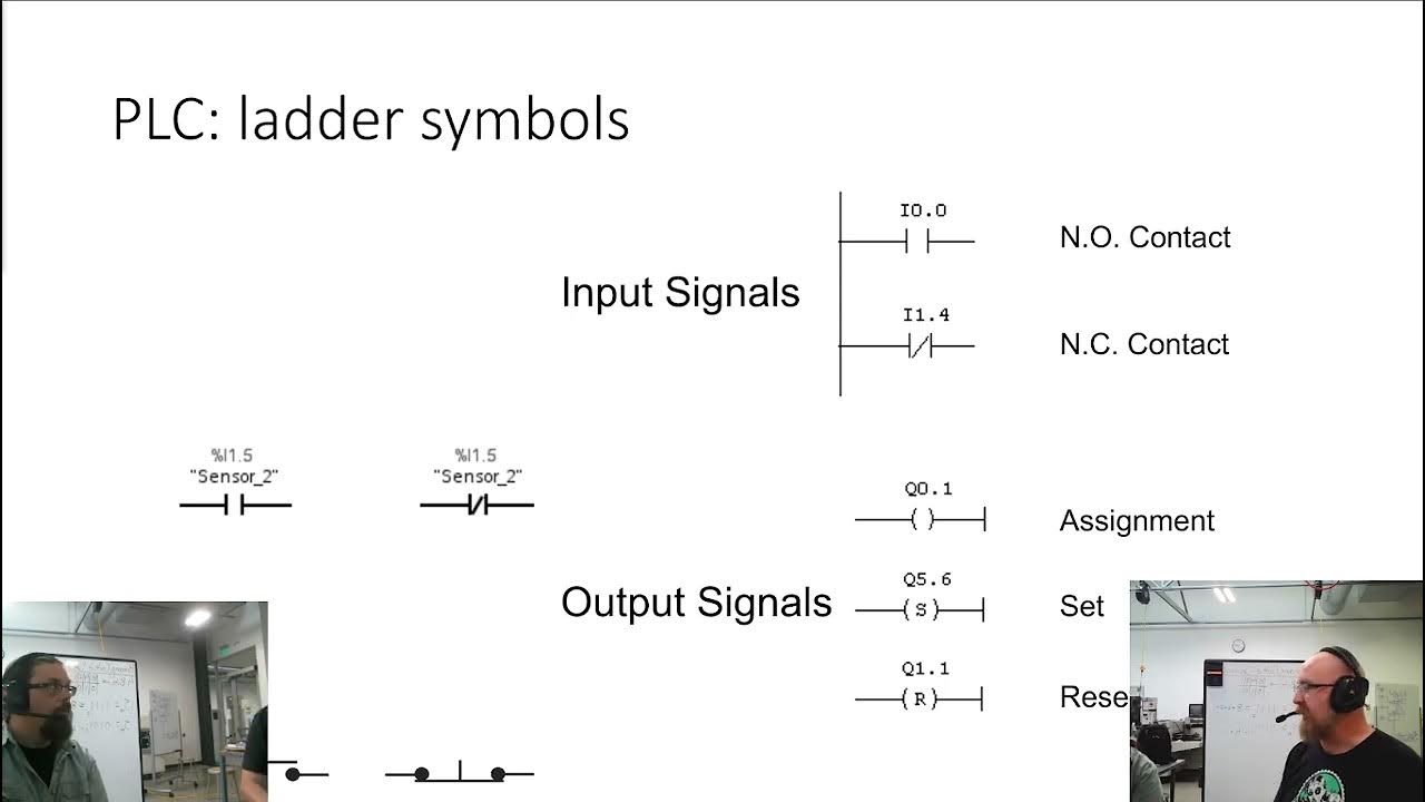
- 📊 Basic symbols in ladder diagrams include normally open contacts, normally closed contacts, and coils, which are essential for constructing the logic.
- 🔄 An example is given on how to convert a simple electrical circuit into a ladder diagram, including the use of contacts in series and parallel configurations.
Q & A
What is the main focus of the YouTube video script?
-The main focus of the YouTube video script is to discuss the programming of PLCs, specifically the Siemens S7 1200 and 1500 models, using the Ladder Diagram (LD) programming language.
What does the acronym 'LD' stand for in the context of the script?
-In the script, 'LD' stands for Ladder Diagram, which is a graphical programming language used for programming PLCs.
Why is the Ladder Diagram language commonly used by PLC programmers?
-The Ladder Diagram language is commonly used by PLC programmers because it closely resembles electrical schematics, making it intuitive for those familiar with electrical systems.
What are the two categories of PLC programming languages according to IEC 1131-3?
-According to IEC 1131-3, PLC programming languages are divided into two categories: textual languages and graphical languages.
What are the textual PLC programming languages mentioned in the script?
-The textual PLC programming languages mentioned in the script are 'Structured Text' (ST) and 'Sequential Function Chart' (SFC).
What are the graphical PLC programming languages mentioned in the script?
-The graphical PLC programming languages mentioned in the script are 'Ladder Diagram' (LD), 'Function Block Diagram' (FBD), and 'Sequential Function Chart' (SFC).
What does the term 'rung' mean in the context of Ladder Diagrams?
-In Ladder Diagrams, 'rung' refers to a horizontal line on which the logic for controlling a particular system is drawn.
How does the logical flow differ between functional electrical schematics and Ladder Diagrams?
-In functional electrical schematics, the logical flow goes from left to right, whereas in Ladder Diagrams, it flows from top to bottom.
What is the significance of the vertical lines in a Ladder Diagram?
-The vertical lines in a Ladder Diagram represent the power supply rails, similar to the '+' and '-' in an electrical schematic.
How does one convert an electrical schematic to a Ladder Diagram?
-To convert an electrical schematic to a Ladder Diagram, one rotates the schematic 90 degrees to the right and replaces electrical contacts with their Ladder Diagram symbols.
What is the purpose of the horizontal lines in a Ladder Diagram?
-The horizontal lines in a Ladder Diagram, known as 'rungs', are where the logic for inputs and outputs is laid out, with inputs typically on the left and outputs on the right.
Outlines

Cette section est réservée aux utilisateurs payants. Améliorez votre compte pour accéder à cette section.
Améliorer maintenantMindmap

Cette section est réservée aux utilisateurs payants. Améliorez votre compte pour accéder à cette section.
Améliorer maintenantKeywords

Cette section est réservée aux utilisateurs payants. Améliorez votre compte pour accéder à cette section.
Améliorer maintenantHighlights

Cette section est réservée aux utilisateurs payants. Améliorez votre compte pour accéder à cette section.
Améliorer maintenantTranscripts

Cette section est réservée aux utilisateurs payants. Améliorez votre compte pour accéder à cette section.
Améliorer maintenantVoir Plus de Vidéos Connexes

Überblick Siemens Simatic SPS Hardware - SPS programmieren lernen - Online Grundkurs (Kapitel 1.2)

Truyền thông PROFINET S7-1200/1500 với nhiều PLC và thiết bị các hãng khác nhau thành 1 dây chuyền.
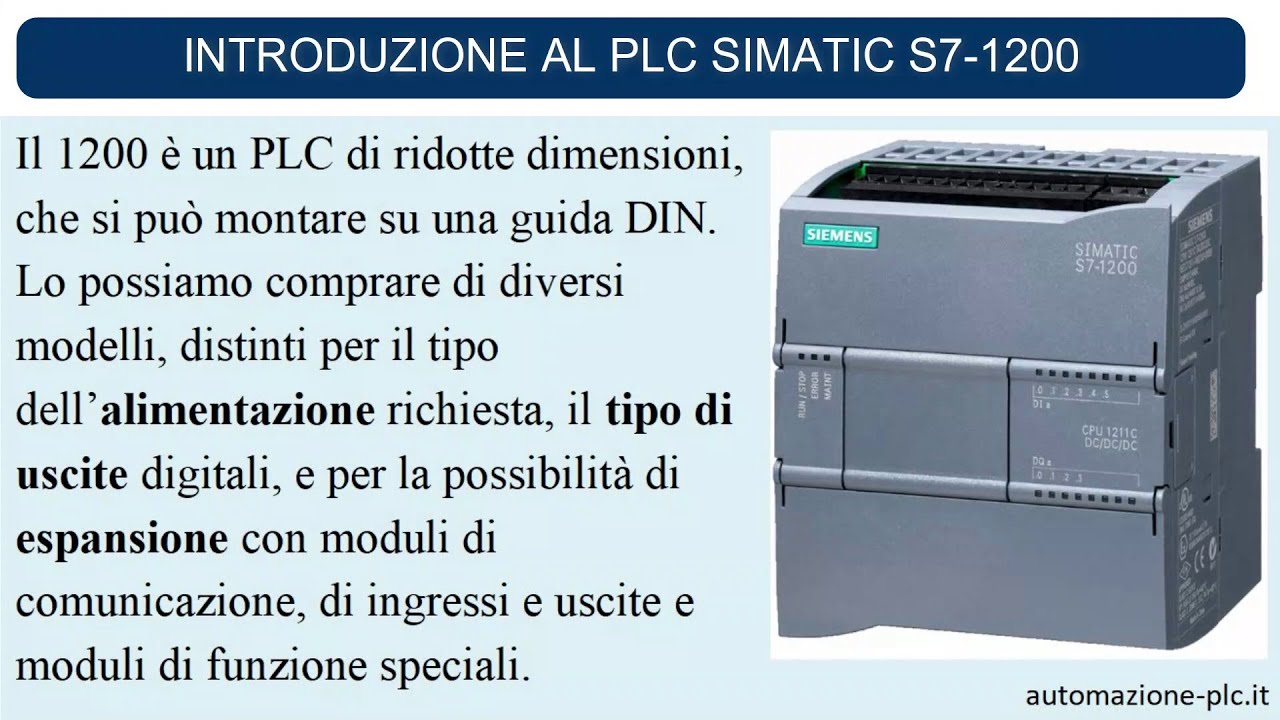
Introduzione al plc Simatic S7-1200 Siemens

Belajar PLC | 5 Tipe Bahasa Pemrograman PLC

Ladder Logic Diagrams for PLCs | Industrial Automation
SysAp 7 1 Ladder Logic
5.0 / 5 (0 votes)
