VHDL Lecture 4 Lab1-Switches LEDs Simulation
Summary
TLDRIn this video, the process of creating and testing a VHDL program to control LEDs using switches is demonstrated. The presenter walks through setting up a VHDL test bench, removing unnecessary clock definitions, and initializing inputs (switches) with different combinations of states. The test bench uses a 'wait' statement to simulate delays and verify the system's response. The simulation shows how the LED outputs change based on the input switch states, confirming the correct behavior of the VHDL code. The lab provides a practical guide for testing VHDL code in a simulated environment to ensure it meets expected functionality.
Takeaways
- 😀 The lab focuses on writing VHDL code to control LEDs using switches.
- 😀 Test benches are essential in VHDL to simulate and test the functionality of the code before implementation.
- 😀 A test bench is created by right-clicking on the entity and selecting 'VHDL Test Bench' in the VHDL project.
- 😀 It's a good practice to name the test bench file with 'TB' for Test Bench, though it’s not mandatory.
- 😀 Predefined clock components from Xilinx are removed from the test bench since they are unnecessary for this project.
- 😀 The main task in the test bench is to simulate various input states, which are the switch values, to test the LEDs.
- 😀 The 'wait for' statement in VHDL is used to introduce delays between different input states in the test bench.
- 😀 The test bench covers four switch combinations: 00, 01, 10, and 11, with a 10 ns delay for each change.
- 😀 The simulation mode in the VHDL tool must be selected to run the simulation and check the outputs.
- 😀 The simulation window shows the effects of the switch values on the LEDs, confirming that the code works as expected.
Q & A
What is the purpose of a testbench in VHDL programming?
-A testbench in VHDL is used to simulate and verify the functionality of VHDL code before implementing it on hardware. It helps in testing the logic of the design by providing input stimuli and checking the outputs without needing actual hardware.
How do you create a testbench in Xilinx software?
-To create a testbench in Xilinx software, right-click on the entity name, select 'New Source', choose 'VHDL Testbench', provide a file name (usually including 'TB' for testbench), and click 'Next' to finish the setup. The software will generate the necessary code structure for the testbench.
Why do you need to delete predefined clock lines in the testbench?
-In this specific case, there is no need for a clock in the simulation, so predefined clock lines created by Xilinx software need to be deleted. This helps to avoid unnecessary clock behavior and focus only on testing the LEDs and switches functionality.
What does the 'wait for 10 ns' statement do in the testbench?
-The 'wait for 10 ns' statement in the testbench pauses the simulation for a specified amount of time (10 nanoseconds in this case). This ensures that the inputs are stable for the given duration before changing them again.
What are the possible input combinations used in this simulation?
-The input combinations tested in the simulation are 00, 01, 10, and 11 for the two switches. Each combination is tested sequentially, with a pause (using 'wait') between changes.
What is the significance of initializing the inputs to zero in the testbench?
-Initializing the inputs to zero ensures that the simulation starts with a known state, which allows for consistent and repeatable results when testing the behavior of the LEDs in response to different input combinations.
How does the simulation verify the LED control functionality?
-The simulation verifies LED control by observing the output LEDs' states corresponding to the input switches. If the LEDs behave as expected based on the switches' values, the simulation confirms that the code works correctly.
What happens after initializing the switches in the testbench?
-After initializing the switches, the state of each switch is changed sequentially (e.g., 00, 01, 10, 11) with corresponding waits. The simulation then checks the LED outputs to see if they match the expected behavior.
What does the 'simulate behavioral' button do in the simulation process?
-The 'simulate behavioral' button runs the simulation using the testbench, executing the test cases defined in the testbench and showing the results in a simulation window, allowing you to verify the functionality of your VHDL code.
How do you interpret the results from the simulation window?
-The results are interpreted by observing the time-frame outputs. For example, when a switch is toggled, you can verify if the corresponding LED turns on or off as expected. The simulation shows a timeline with values for the switches and LEDs, confirming if the design behaves as intended.
Outlines

Esta sección está disponible solo para usuarios con suscripción. Por favor, mejora tu plan para acceder a esta parte.
Mejorar ahoraMindmap

Esta sección está disponible solo para usuarios con suscripción. Por favor, mejora tu plan para acceder a esta parte.
Mejorar ahoraKeywords

Esta sección está disponible solo para usuarios con suscripción. Por favor, mejora tu plan para acceder a esta parte.
Mejorar ahoraHighlights

Esta sección está disponible solo para usuarios con suscripción. Por favor, mejora tu plan para acceder a esta parte.
Mejorar ahoraTranscripts

Esta sección está disponible solo para usuarios con suscripción. Por favor, mejora tu plan para acceder a esta parte.
Mejorar ahoraVer Más Videos Relacionados
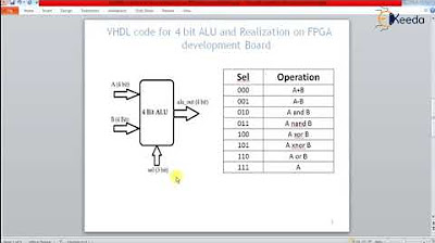
VHDL code for 4 bit ALU and Realization on FPGA development Board
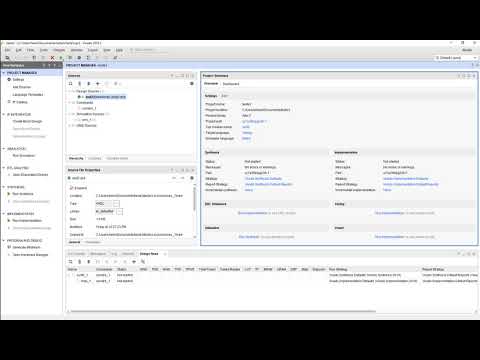
Vivado01 1 Familiarizacao com o Vivado e Simulacao de uma AND2
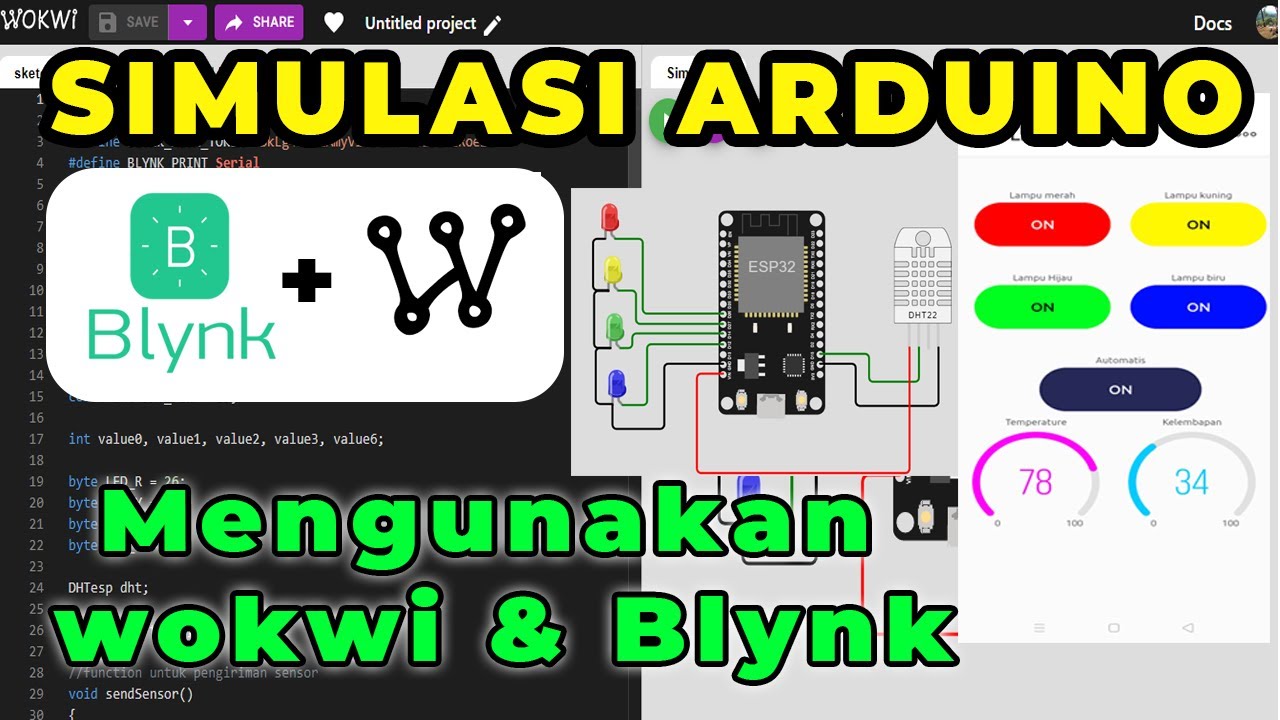
SIMULASI WOKWI MENGUANKAN BLYNK ARDUINO
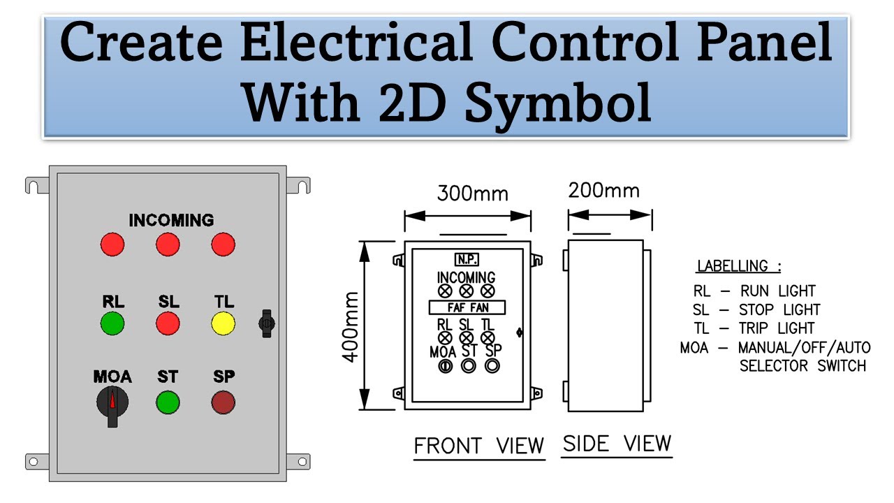
Create Electrical Control Panel Revit Family including 2D Symbol
Optix Basics: Build & Animate Basic Graphics

Faça uma PLACA SOLAR usando LEDs COMUNS!
5.0 / 5 (0 votes)
