Create Electrical Control Panel Revit Family including 2D Symbol
Summary
TLDRIn this tutorial, the process of creating an electrical control panel with 2D symbols in Revit is demonstrated. The video guides users through the steps of creating a main family and a 2D symbol family, adding parameters, and inserting different electrical components such as pilot lights, buttons, and switches. The tutorial also covers the use of work planes, extrusion, and material settings. By the end, viewers learn how to load the created families into a project, set electrical connectors, and test the design in a Revit project.
Takeaways
- 😀 Start by creating an electrical control panel with two families: the main family for the panel and a 2D symbol family.
- 😀 Ensure the main family is set under the **Electrical Equipment** category with a **Panel Board** part type.
- 😀 Use reference planes and create parameters for the panel's length, height, and depth to set its dimensions.
- 😀 Create extrusions to form the panel's structure and lock the sketch paths to the reference planes.
- 😀 Add mounting brackets, pilot lights, selector switches, and various buttons (start, stop) as components to the panel.
- 😀 Customize the text on the panel with model text, set its size, and apply the appropriate material and appearance.
- 😀 Create a 2D symbol family using a **Generic Detail Item** template, and use reference planes to set the symbol’s dimensions.
- 😀 Draw a rectangle for the 2D symbol and use a filled region to represent its visual elements.
- 😀 Load the created 2D family into the main family, ensuring everything is aligned and locked properly.
- 😀 Add an electrical connector to the top of the panel and load the family into a test project to check its functionality.
- 😀 Finalize the process by adjusting visibility settings, checking the family in 3D view, and performing a final review.
Q & A
What is the first step in creating an electrical control panel in Revit?
-The first step is to open a new family in Revit and select the 'Generic Model Face-Based' template. After that, you need to set the family category to 'Electrical Equipment' and select 'Panel Board' as the part type.
How do you set up the reference planes for the panel's dimensions?
-You start by selecting the existing reference plane and setting an offset of 150 mm for the length and 200 mm for the height. You then insert dimensions, make them equal, and add parameters for these dimensions, selecting 'Instance' for flexibility.
What tools are used to create the 3D geometry of the panel?
-The 'Extrusion Sketch Path' tool is used to create the 3D geometry of the panel. The extrusions are locked to the reference planes to ensure the geometry remains aligned properly.
How do you add components like pilot lights and buttons to the panel?
-You insert various components such as pilot lights, selector switches, and buttons by loading their corresponding families into the main family. After placing them, align them to the reference planes and lock them in place to maintain consistent positioning.
How can you ensure the components are properly aligned in the panel?
-You can align components to the reference planes using the 'Align' tool and lock them to maintain their positions. This ensures the components remain in the correct location when changes are made to the panel.
What is the process for creating the 2D symbol for the panel?
-To create the 2D symbol, you start a new family with the 'Generic Detail Item' template, set up reference planes, draw a rectangle using the 'Line' tool, and fill the area with a 'Filled Region'. Then, adjust the color and finish the symbol.
How do you add text to the panel for identification?
-You add text by using the 'Model Text' tool. Set the font size, align the text to the center horizontally, and apply materials to it. The text can also be duplicated and placed for additional labeling or identification.
What is the role of the electrical connectors in the panel?
-Electrical connectors are used to define the electrical load data for the panel. These connectors allow the panel to be integrated into the electrical system, enabling the necessary connections for functionality.
How do you load the created panel into a project in Revit?
-To load the panel into a project, open a new project (using the Mechanical Template, for example), insert a wall to mount the panel, and adjust the view range settings. Then, load the created family into the project and check the visibility of the electrical equipment.
How do you ensure the proper display of the panel in different views?
-You can check the display of the panel in 3D view and adjust its visibility using the 'Visibility/Graphics' (VG) settings. Additionally, you can create sections to inspect the panel in various perspectives, ensuring that all components are visible and properly positioned.
Outlines

This section is available to paid users only. Please upgrade to access this part.
Upgrade NowMindmap

This section is available to paid users only. Please upgrade to access this part.
Upgrade NowKeywords

This section is available to paid users only. Please upgrade to access this part.
Upgrade NowHighlights

This section is available to paid users only. Please upgrade to access this part.
Upgrade NowTranscripts

This section is available to paid users only. Please upgrade to access this part.
Upgrade NowBrowse More Related Video

Revit - Tutorials for Beginners in 10 MINUTES ! [ FULL GUIDE 2024 ]
3D bracket with Solid and Surface tools of AutoCAD
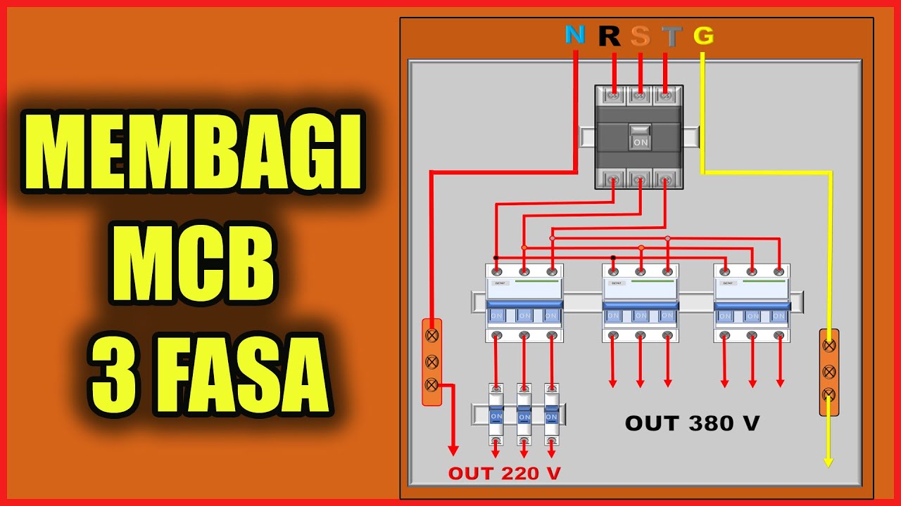
CARA MEMBAGI MCB 3 FASA DAN 1 FASA

Cara Membuat Rangkaian Panel Starter Genset AMF Automatic Main Failure
TUTORIAL BIM REVIT STRUKTUR SMK PART 20 | DPIB SMKN 1 JAKARTA - PONDASI BATU KALI

Revit Tutorial Deutsch - Einführung und Grundlagen
5.0 / 5 (0 votes)