VCVS: Voltage Controlled Voltage Source
Summary
TLDRIn this video, the speaker walks through a detailed example of analyzing a voltage-controlled voltage source circuit, focusing on how to determine voltage drops and power dissipation. By applying Kirchhoff's Current Law, Kirchhoff's Voltage Law, and Ohm's Law, the speaker guides the viewer through the process of calculating current, voltage, and power at various points in the circuit. The tutorial emphasizes the importance of correctly applying these principles, confirming the solution with power balance, and offering a clear explanation of both dependent and independent power sources in a practical circuit analysis scenario.
Takeaways
- 😀 The video covers an example of a voltage-controlled voltage source, a type of dependent power source.
- 😀 The goal of the example is to determine the voltage drops across each element, as well as the power dissipation in resistors and power delivery into the circuit.
- 😀 The voltage-controlled voltage source provides a voltage that is one quarter of the voltage of the controlling voltage, which is the voltage across an element.
- 😀 Kirchhoff's Current Law (KCL), Kirchhoff's Voltage Law (KVL), and Ohm's Law are applied throughout the problem to solve for the unknowns.
- 😀 The current through each branch of the circuit is determined based on the independent current sources (1 amp and 2 amps), and Kirchhoff’s Current Law ensures that the total current in and out of a node is balanced.
- 😀 Ohm’s Law is used to calculate the voltage drop across the 4-ohm resistor, which results in a voltage drop of 12 volts across the resistor.
- 😀 The voltage across the dependent power source is calculated to be 3 volts, based on the controlling voltage.
- 😀 The voltage at different junctions is labeled relative to a chosen ground, helping to determine the potential differences in the circuit.
- 😀 Power dissipation in resistors is calculated using the formula P = V x I, with results showing 9 watts for the 1-ohm resistor and 36 watts for the 4-ohm resistor.
- 😀 The total power dissipation in the resistors is 45 watts, while the total power delivered to the circuit by the power sources is also -45 watts, indicating energy conservation in the circuit.
Q & A
What is the main objective of the video?
-The main objective is to explain how to calculate the voltage drops, current, and power dissipation in a circuit involving dependent and independent power sources, specifically focusing on a voltage-controlled voltage source.
What role does the dependent power source play in the circuit?
-The dependent power source in the circuit provides a voltage that is a fraction (one-quarter) of the controlling voltage across a specified element in the circuit.
How do we determine the voltage drop across the 4-ohm resistor?
-Using Ohm's law, the voltage drop across the 4-ohm resistor is calculated by multiplying the current (3 amps) by the resistance (4 ohms), giving a voltage drop of 12 volts.
What is the controlling voltage for the dependent power source?
-The controlling voltage for the dependent power source is the voltage across the 4-ohm resistor, which was determined to be 12 volts.
How do we calculate the current through the 1-ohm resistor?
-The current through the 1-ohm resistor is calculated by applying Ohm's law, using the known voltage drop (3 volts) and dividing it by the resistance (1 ohm), resulting in a current of 3 amps.
How does Kirchhoff’s Current Law (KCL) apply to this circuit?
-KCL states that the sum of currents entering a node must equal the sum of currents leaving the node. In this circuit, currents entering and leaving each node are balanced, ensuring conservation of current at each junction.
What are the power dissipation values for the resistors in the circuit?
-The power dissipation for the 1-ohm resistor is 9 watts (3 volts × 3 amps), and for the 4-ohm resistor, it is 36 watts (12 volts × 3 amps). The total power dissipation from the resistors is 45 watts.
How do we calculate the power delivered by the independent current sources?
-The power delivered by the independent current sources is calculated using the formula P = V × I. For the first independent current source, the power is negative 24 watts (12 volts × -2 amps), and for the second one, it’s negative 9 watts (9 volts × -1 amp).
Why do we treat current entering the negative terminal as negative in the power formula?
-We treat current entering the negative terminal as negative in the power formula because of the passive sign convention, which helps ensure that the power delivered by the source is correctly represented as a negative value when it’s supplying power to the circuit.
What does it mean when the total power delivery and dissipation sum to zero?
-When the total power delivery and dissipation sum to zero, it indicates that the energy supplied by the power sources is exactly equal to the energy dissipated by the resistors, confirming that the circuit is balanced and adhering to the law of conservation of energy.
Outlines

此内容仅限付费用户访问。 请升级后访问。
立即升级Mindmap

此内容仅限付费用户访问。 请升级后访问。
立即升级Keywords

此内容仅限付费用户访问。 请升级后访问。
立即升级Highlights

此内容仅限付费用户访问。 请升级后访问。
立即升级Transcripts

此内容仅限付费用户访问。 请升级后访问。
立即升级浏览更多相关视频

High School Physics - Series Circuits
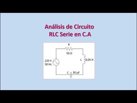
Análisis de Circuitos RLC en Corriente Alterna. Diagrama Fasorial. Ejercicio Resuelto.
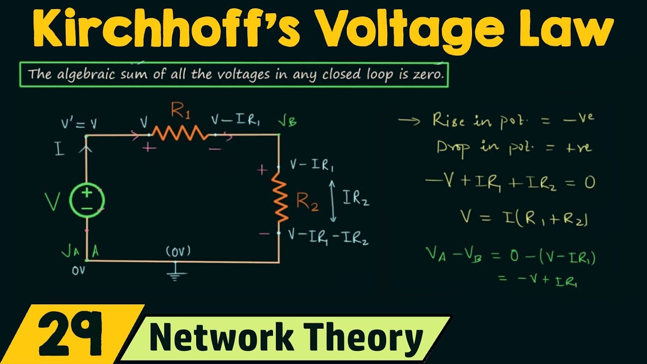
Kirchhoff's Voltage Law (KVL)

Zener Diode Regulators: Lecture: Part 1 V4VP2 ELE424 DL

Kirchhoff's voltage law | Circuit analysis | Electrical engineering | Khan Academy
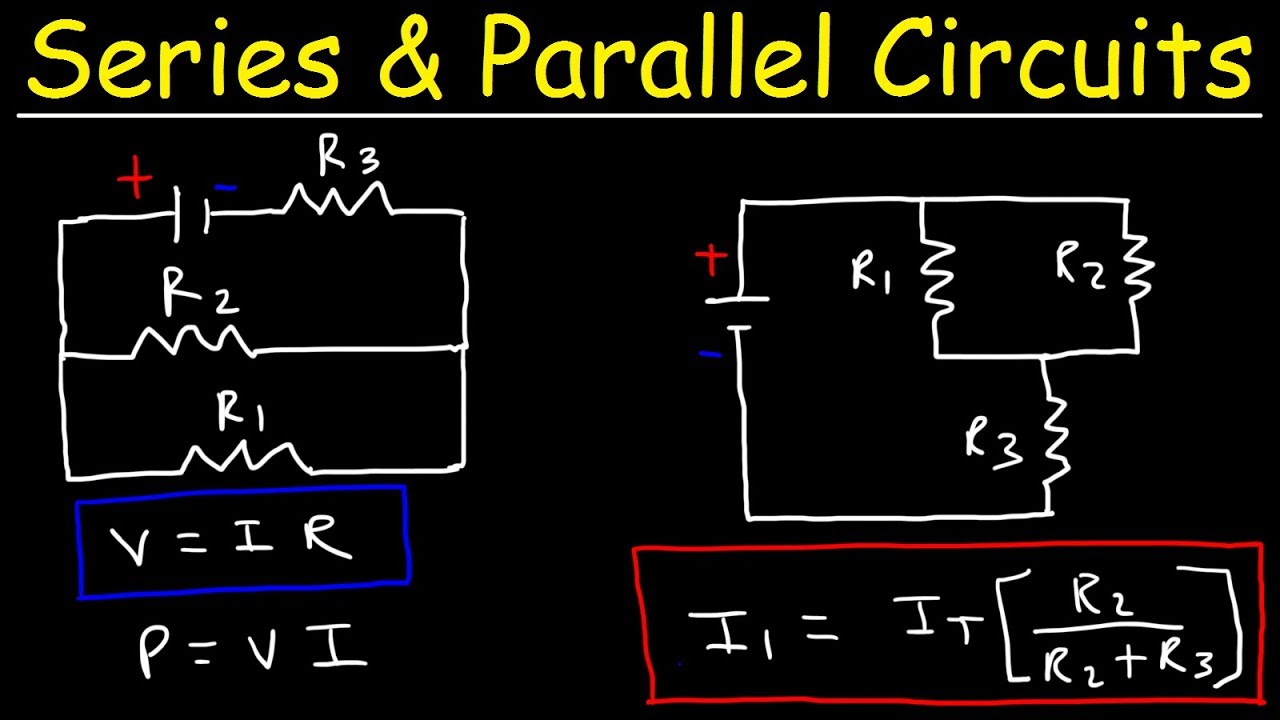
Resistors In Series and Parallel Circuits - Keeping It Simple!
5.0 / 5 (0 votes)
