Análisis de Circuitos RLC en Corriente Alterna. Diagrama Fasorial. Ejercicio Resuelto.
Summary
TLDRThis video tutorial explains the analysis of an RLC series circuit in an alternating current system. The presenter walks through the calculation of total impedance, current, and voltage drops across the resistor, inductor, and capacitor. Using Ohm's law, they calculate the total impedance and its components, determine the current and its phase angle, and analyze the voltage drops in each component. The video concludes with a detailed explanation of how to verify the results using Kirchhoff's Voltage Law through vector diagrams, ensuring the sum of voltage drops matches the supply voltage.
Takeaways
- 😀 The video provides an analysis of a series RLC circuit in alternating current (AC), detailing the process to determine total impedance, current, and voltage drops across various components.
- 😀 The main goal of the exercise is to determine the total impedance (Z), the current, the voltage drops across the resistor, inductor, and capacitor, and to construct a phasor diagram for the circuit.
- 😀 The circuit is powered by a 220V AC source with a frequency of 50 Hz, and consists of a 50-ohm resistor, a 0.5-henry inductor, and a 30-microfarad capacitor.
- 😀 Ohm's law is applied to determine the total current in the circuit, where the voltage from the source is divided by the total impedance (Z).
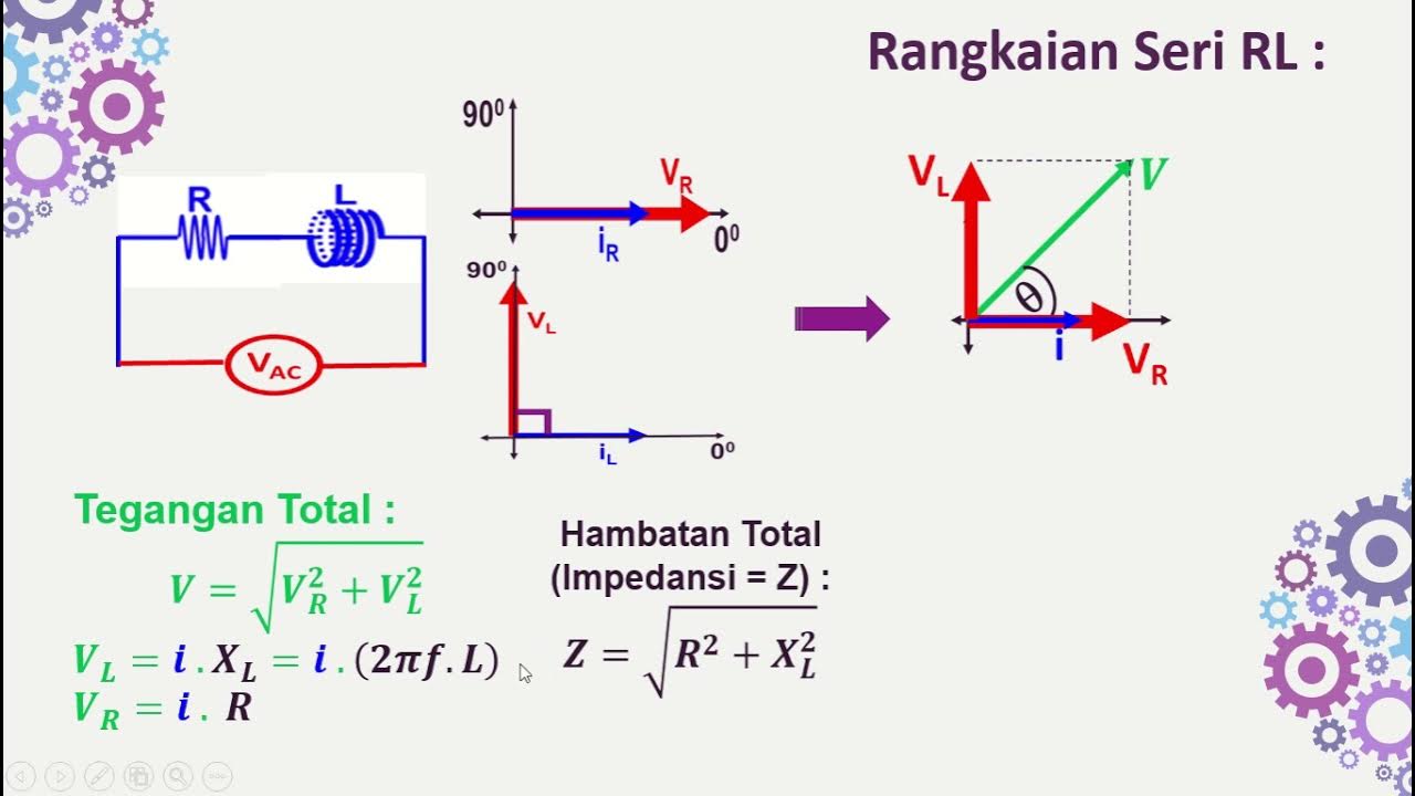
- 😀 The total impedance is the sum of the resistive impedance and the reactive impedances from the inductor and capacitor, expressed as Z = R + j(X_L - X_C).
- 😀 The inductive reactance (X_L) is calculated as 157 ohms, and the capacitive reactance (X_C) is calculated as 106.1 ohms.
- 😀 The total reactance is found by subtracting the capacitive reactance from the inductive reactance, resulting in a total reactance of 50.9 ohms.
- 😀 Using the impedance diagram, the total impedance is calculated as 71.3 ohms with an angle of 45.5 degrees, indicating that the impedance is inductive and resistive.
- 😀 The current is calculated using Ohm’s law, yielding a value of 308A with an angle of -45.5 degrees.
- 😀 The voltage drops across the resistor, inductor, and capacitor are calculated by multiplying the current with their respective impedances, and the results are presented in phasor form for visualization.
Q & A
What is the main objective of the analysis presented in the video?
-The main objective is to analyze an RLC series circuit in alternating current (AC), determining the total impedance, current, voltage drops across the resistor, inductor, and capacitor, and constructing the impedance diagram.
How is the total impedance of the circuit calculated?
-The total impedance of the circuit is calculated by summing the impedance of each component: the resistor (R), inductor (XL), and capacitor (XC). The total impedance is expressed as Z = R + j(XL - XC), where j represents the imaginary unit.
What formula is used to calculate the inductive reactance (XL)?
-The inductive reactance (XL) is calculated using the formula XL = 2πfL, where f is the frequency of the circuit and L is the inductance of the inductor.
How is the capacitive reactance (XC) determined?
-The capacitive reactance (XC) is calculated using the formula XC = 1 / (2πfC), where f is the frequency of the circuit and C is the capacitance of the capacitor.
What is the significance of the angle in the total impedance?
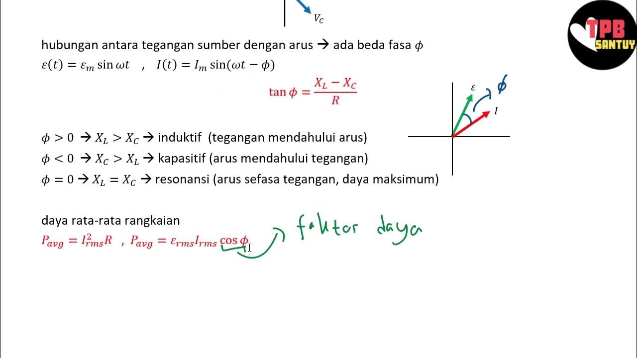
-The angle of the total impedance represents the phase difference between the total current and the total voltage in the circuit. A positive angle indicates the circuit is inductive, meaning the current lags behind the voltage.
How is the current in the circuit calculated?
-The current is calculated using Ohm's law for AC circuits, which states that the current is the source voltage divided by the total impedance. The formula is I = V / Z, where V is the source voltage and Z is the total impedance.
What does the negative angle of the total current indicate?
-The negative angle of the total current indicates that the current lags the voltage, which is typical of a circuit with inductive reactance.
How is the voltage drop across the resistor calculated?
-The voltage drop across the resistor is calculated by multiplying the current (in polar form) by the resistance (R). Since the current and voltage are in phase for the resistor, the angle of the voltage drop is the same as the current's angle.
Why are the voltage drops across the inductor and capacitor higher than the source voltage?
-The voltage drops across the inductor and capacitor are higher than the source voltage because these voltages are calculated as phasors, not scalars. The individual voltages in the components can have different phases, leading to higher voltages in these reactive components.
How is the voltage drop across the inductor and capacitor verified using Kirchhoff's Voltage Law?
-The voltage drop across each component is verified by summing the voltage drops vectorially. According to Kirchhoff's Voltage Law (KVL), the sum of the voltage drops in the loop must equal the source voltage. The individual drops in the inductor, resistor, and capacitor are summed to check if they equal the total source voltage.
Outlines

This section is available to paid users only. Please upgrade to access this part.
Upgrade NowMindmap

This section is available to paid users only. Please upgrade to access this part.
Upgrade NowKeywords

This section is available to paid users only. Please upgrade to access this part.
Upgrade NowHighlights

This section is available to paid users only. Please upgrade to access this part.
Upgrade NowTranscripts

This section is available to paid users only. Please upgrade to access this part.
Upgrade NowBrowse More Related Video
FISIKA KELAS XII | RANGKAIAN ARUS BOLAK-BALIK (AC) - PART 2 : RANGKAIAN RLC

AC Through Series RC Circuit - AC Circuits - Basic Electrical Engineering
Rangkaian Seri RLC | Rangkaian AC | Part 2 | Fisika Dasar
Rangkaian Seri RL-RC-LC dengan Sumber AC

Lesson 1 - What Is Alternating Current? (AC Circuit Analysis)
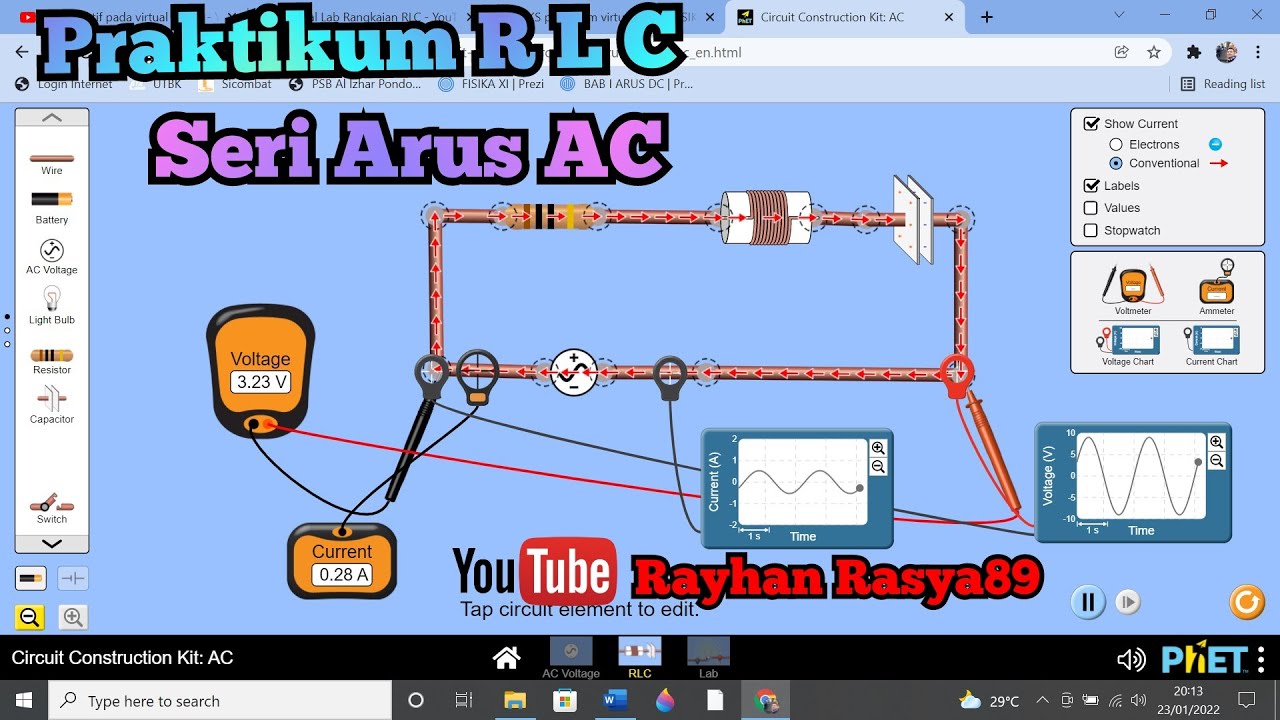
Praktikum RANGKAIAN RLC SERI PADA ARUS AC menggunakan Virtual Lab PHET.
5.0 / 5 (0 votes)