Cara Mudah Memahami Usecase Diagram pada Matakuliah RPL
Summary
TLDRIn this video, the instructor discusses software requirements analysis and UML (Unified Modeling Language) diagrams, focusing on use case diagrams. The session highlights the key stages in analyzing software requirements, including problem definition, solution offerings, and functional vs non-functional requirements. The instructor explains various UML diagram types, such as behavior, structure, and interaction diagrams, with a primary focus on use case diagrams. Detailed explanations of actor relationships, symbols, use cases, and the extend/include mechanisms are provided to help understand system functionalities and interactions. Real-world examples are given to illustrate how these concepts apply to system design.
Takeaways
- 😀 Understanding the importance of Software Requirements Analysis: It is the first step in software development, defining the user's needs before software development can begin.
- 😀 Three essential factors for good software requirements: Completeness, Detail, and Accuracy.
- 😀 Two main categories in Software Requirements Analysis: Functional Requirements (features/services) and Non-functional Requirements (system constraints).
- 😀 UML (Unified Modeling Language) is a standard for modeling, visualizing, and documenting software systems. It is essential for designing software architectures.
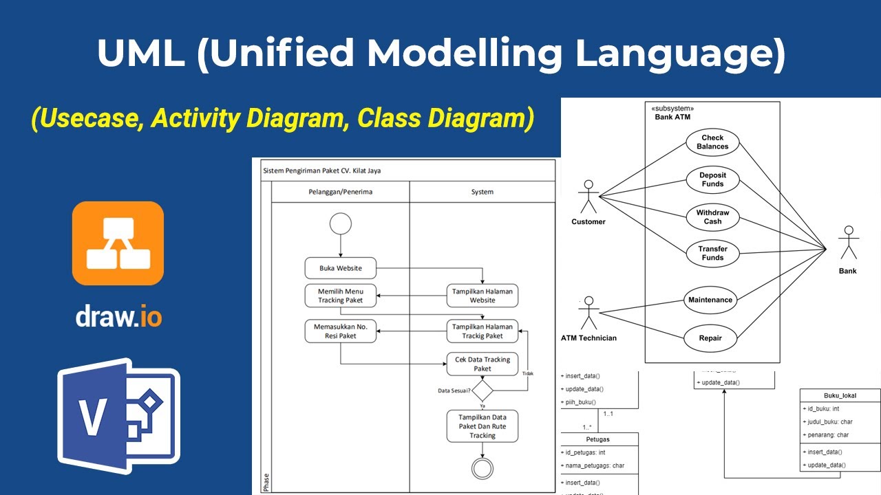
- 😀 UML diagrams are divided into three types: Behavior Diagrams, Structure Diagrams, and Interaction Diagrams.
- 😀 Behavior Diagrams represent the dynamic behavior of systems, with use case diagrams, activity diagrams, and state diagrams as examples.
- 😀 Structure Diagrams focus on the static structure of a system, including class diagrams, object diagrams, and deployment diagrams.
- 😀 Interaction Diagrams depict the interactions between systems or subsystems, with sequence diagrams and communication diagrams being part of this category.
- 😀 Use Case Diagrams are central in UML: They define what the system will do from the user's perspective, identifying the interaction between actors and the system.
- 😀 Key elements of Use Case Diagrams include actors, use cases, associations, and relationships such as extend, include, and generalization.
- 😀 Extensions (extend) and inclusions (include) describe optional and mandatory actions respectively, highlighting the conditional relationships between use cases.
Q & A
What is the main topic of the tutorial?
-The main topic of the tutorial is about UML (Unified Modeling Language), specifically Use Case Diagrams, and their application in software development.
What are the two types of software requirements mentioned in the video?
-The two types of software requirements mentioned are functional requirements (what the system should do) and non-functional requirements (constraints on the system, such as performance and security).
What are the three factors that ensure software requirements are good?
-The three factors that ensure good software requirements are completeness, detail, and correctness.
What is the role of UML in software development?
-UML is used to visualize, design, and document software systems. It provides a standardized way to model systems, making it easier to communicate and develop software.
What are the three categories of UML diagrams?
-The three categories of UML diagrams are: 1) Behavior Diagrams, 2) Structure Diagrams, and 3) Interaction Diagrams.
What does a Use Case Diagram model?
-A Use Case Diagram models the functionalities of a system and the interactions between actors (users or systems) and the system itself.
What is the difference between 'extend' and 'include' relationships in Use Case Diagrams?
-'Extend' represents optional behavior that can be added to a use case, while 'Include' represents a mandatory behavior that must happen as part of the use case.
How does 'generalization' work in Use Case Diagrams?
-In Use Case Diagrams, generalization represents a hierarchical relationship where a more general use case is shared by more specific use cases. The arrows point from the specific use case to the general one.
Can you give an example of a Use Case Diagram based on the script?
-An example from the script is a restaurant system, where actors like 'Customer' and 'Cashier' perform actions such as choosing a menu and making payments, while the manager can handle reports, all of which may require a login (Include relationship).
What tools are recommended for creating UML diagrams?
-Some tools recommended for creating UML diagrams include Star UML, Agrol, RAL, Miro, and Paradigm. Users can choose tools that are either free or paid, depending on their needs.
Outlines

此内容仅限付费用户访问。 请升级后访问。
立即升级Mindmap

此内容仅限付费用户访问。 请升级后访问。
立即升级Keywords

此内容仅限付费用户访问。 请升级后访问。
立即升级Highlights

此内容仅限付费用户访问。 请升级后访问。
立即升级Transcripts

此内容仅限付费用户访问。 请升级后访问。
立即升级浏览更多相关视频

Rekayasa Perangkat Lunak - Pemodelan Sistem
Apa itu UML? Beserta Pengertian dan Contohnya | Belajar UML & Perancangan Sistem

Project Based Internship Klinikgo Health System Analyst - Company Coaching Video 1
Introduction to UML

TOPCIT Software | 05. Software Requirements Analysis

Use Case Dengan EA Sparx 1
5.0 / 5 (0 votes)
