TOPCIT Software | 05. Software Requirements Analysis

TOPCIT사업단
24 Aug 201721:40

Summary

TLDRThis script discusses the software development lifecycle, emphasizing the V-model and its iterative phases. It highlights the importance of requirements analysis to enhance communication, reduce defects, and enable code reuse. The video introduces structured analysis and object-oriented methodologies, using examples like the automobile cruise control system and bank deposit services to illustrate the process of creating system context diagrams, data flow diagrams, and use case diagrams. It also touches on the significance of modeling languages like UML in advancing from code-based to model-driven development.

Takeaways

  • πŸ“ˆ The V-model is a fundamental concept in software engineering, illustrating the development lifecycle with various outputs at each phase that are closely related and serve as inputs for subsequent phases.
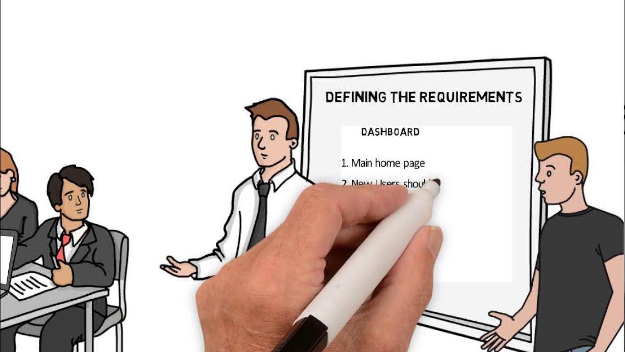
  • πŸ“ System requirements documents are crucial as they reflect all the requirements gathered by marketing and are further developed with internal and external standards and constraints.
  • πŸ” Errors in requirements are a significant cause of rework in the testing phase, with IAG consulting stating that over 40% of the development budget is wasted due to incorrect requirements.
  • πŸ—£οΈ Software requirements analysis and specification activities are vital for improving communication efficiency among developers and reducing development costs by identifying and addressing issues early on.
  • πŸ› οΈ Unified Modeling Language (UML) was developed to facilitate better understanding and communication of complex software structures among developers.
  • πŸ”„ The systematic approach to requirements analysis and specification helps in reducing defects and associated costs by identifying issues early in the development process.
  • πŸ”„ Defects found later in the development process can exponentially increase the cost of fixing and maintaining them, emphasizing the importance of early detection through systematic development.
  • πŸ”„ Source code reuse is a significant advantage of software requirements analysis and specification, especially in complex systems where code-based development has limitations.
  • 🌐 The global trend is moving towards Model-Driven Development (MDD) and Model-Driven Testing (MDT) as a way to overcome the limitations of code-based development techniques.
  • πŸ”§ Structured analysis is commonly used in system analysis and embedded system analysis, focusing on defining the 'what' of the system rather than the 'how', using data flow diagrams and state machine specifications.
  • πŸš— The development process of the automobile cruise control system is used as an example to illustrate the application of structured analysis, emphasizing the importance of understanding system context and decomposing processes.

Q & A

  • What is the V-model in software engineering?

    -The V-model in software engineering is a development lifecycle model that describes the various outputs developed at each phase of the software development process. It emphasizes that outputs from one phase are used as inputs for the next, creating a 'V' shape when visualized.

  • Why are system requirements documents important in the software development lifecycle?

    -System requirements documents are crucial because they reflect all the requirements gathered by marketing and other teams, and they incorporate internal and external standards, constraints, and environmental conditions. They serve as the foundation for developing the product and ensuring that child documents meet all the requirements of the parent document.

  • What is one of the main causes of rework in the testing phase of software development?

    -One of the main causes of rework in the testing phase is errors in the requirements, such as misunderstandings, missing requirements during development, or not reflecting changes in requirements.

  • How much of the total development budget is wasted due to wrong requirements according to IAG consulting?

    -According to IAG consulting, more than 40% of the total development budget is wasted due to wrong requirements.

  • What are the three main effects of analyzing and specifying software requirements?

    -The three main effects are increased efficiency of communication among developers, solving problems in a systematic way to reduce defects and costs, and enabling source code reuse.

  • What is Unified Modeling Language (UML) and why was it created?

    -Unified Modeling Language (UML) is a standard modeling language used in software engineering to visualize and specify the design of a system. It was created to make it easier to understand and communicate with the system when many developers are working on it simultaneously.

  • What is the significance of structured analysis in system analysis and embedded system analysis?

    -Structured analysis is significant because it focuses on defining what the system should do by analyzing the requirements and constructing a specification for the logical function. It identifies the information flow between functions without focusing on the specific details of the functions to be implemented.

  • What is a data flow diagram (DFD) and why is it used in structured analysis?

    -A data flow diagram (DFD) is a visual representation that emphasizes the flow of information and deliberately ignores the control sequence. It is used in structured analysis to express information flow between functions more concisely.

  • What is the role of a state machine specification in embedded system analysis?

    -A state machine specification is used in embedded system analysis to explicitly show cases and events that might occur in the future. It helps in expressing analysis and decisions on various combinations without missing any potential scenarios, thus preventing defects.

  • Can you explain the structured analysis process as described in the script?

    -The structured analysis process involves creating a system context diagram to understand overall system behavior, performing stepwise decomposition to break down processes across multiple levels, and creating a process specification for each process by detailing inputs, outputs, and contents.

  • What is the purpose of creating a system context diagram in the development of the automobile cruise control system?

    -The purpose of creating a system context diagram is to illustrate the extent to which the automobile cruise control system interacts with the car and to understand the overall system behavior and context based on the given requirements and system configuration.

  • What is the importance of a data dictionary in the development process?

    -A data dictionary is important as it defines the details of the data shown in the data flow diagram. It includes meaningful information for future design, such as the range of values, and is essential for understanding the inputs and outputs of each process.

  • How does object-oriented development methodology differ from structured analysis in terms of requirements analysis?

    -Object-oriented development methodology focuses on identifying actors and their goals, creating use cases to express the relationship between actors and system functionalities, and using diagrams like use case diagrams to represent these relationships. It differs from structured analysis, which uses data flow diagrams and focuses on information flow and system functions.

  • What is the purpose of a sequence diagram in object-oriented development?

    -A sequence diagram in object-oriented development is used to represent the dynamic behavior of the system. It shows the interactions between objects over time, including the sequence of messages passed between them and the responsibilities assigned to each object during specific events.

  • Why is it important to write a requirements specification based on industry standards?

    -Writing a requirements specification based on industry standards ensures clarity, verifiability, and consistency in the description of how the input is transformed into output. It provides developers with all the necessary details to design the system and helps in creating a clear and standardized understanding of the system's functionalities.

  • What is the significance of functional requirements in a software requirements specification?

    -Functional requirements are significant because they include all the details a software developer needs to design the system. They describe the transformation of input into output and are the most important item in the specification, as they must be clear and verifiable.

  • How can the use of diagrams in a requirements specification help in the development process?

    -The use of diagrams in a requirements specification helps in visualizing the system's structure and behavior, making it easier to understand complex relationships and interactions. It also aids in selecting the appropriate diagram based on the application methodology, such as data flow diagrams for structured techniques, use case diagrams for object-oriented methodologies, and process decomposition diagrams for information engineering methodologies.

Outlines

00:00

πŸ“ˆ Software Development Lifecycle and V-Model

This paragraph introduces the software development lifecycle and the V-model, emphasizing the iterative nature of development where outputs from one phase serve as inputs for the next. It discusses the importance of system requirements documents, which should incorporate marketing requirements and corporate standards. It highlights the common issue of rework due to errors in requirements, which can waste over 40% of the development budget. The paragraph underscores the need for effective software requirements analysis and specification to improve communication among developers, enhance development efficiency, and reduce defects and costs.

05:00

πŸ” The Impact of Software Requirements Analysis

This section delves into the benefits of software requirements analysis and specification, such as improved communication and systematic problem-solving to reduce defects and costs. It explains how the complexity of software development can lead to increased defects, which are often discovered late in the development process, resulting in higher costs for correction. The paragraph advocates for systematic development to catch defects early and save on costs. Additionally, it discusses the advantages of source code reuse in model-based development, facilitated by UML, which can lead to higher quality applications and easier code reuse, contrasting this with the limitations of code-based development.

10:02

πŸ›  Structured Analysis and System Development

The paragraph discusses structured analysis, a method commonly used in system and embedded system analysis. It describes the analysis phase's goal to define the 'what' of the system, focusing on information flow rather than specific implementation details. The use of data flow diagrams and state machine specifications is highlighted as a way to express system behavior concisely and to handle unexpected events. The structured analysis process is exemplified by the development of an automobile cruise control system, detailing the steps from system context diagram to data flow diagram and data dictionary creation.

15:04

🏦 Object-Oriented Development for Banking Services

This section presents an object-oriented development approach applied to the creation of a banking system supporting deposit services. It outlines the process of identifying actors and their goals, distinguishing between primary and secondary actors, and setting system boundaries. The development of use cases and use case diagrams is explained, showing how to refine these to include common behaviors and sub-use cases. The paragraph also covers dynamic behavior analysis through sequence diagrams, illustrating the interactions between objects and actors in scenarios such as account opening.

20:05

πŸ“ Writing Software Requirements Specifications

The final paragraph focuses on the process of writing software requirements specifications in accordance with industry standards, using the example of a bank's software requirements. It emphasizes the importance of clear and verifiable functional requirements, which detail how inputs are transformed into outputs. The paragraph suggests using appropriate diagrams based on the development methodology, such as data flow diagrams for structured techniques, use case diagrams for object-oriented methodologies, and process decomposition diagrams for information engineering methodologies. It also touches on the definition and specification of base processes or use cases, including input-output specifications and external interface data.

Mindmap

Keywords

πŸ’‘V-Model

The V-Model is a software development lifecycle model that emphasizes a staged process where each phase is verified before proceeding to the next. In the video, it is described as a framework where various outputs are developed at each phase, with outputs from one phase serving as inputs for the next, ensuring a systematic approach to software development.

πŸ’‘System Requirements Document (SRD)

A System Requirements Document is a key deliverable in software development that outlines the requirements for the system to meet. In the script, it is mentioned as being based on top-level requirements such as marketing requirements, and it should reflect all gathered requirements while also incorporating corporate standards and environmental conditions.

πŸ’‘Unified Modeling Language (UML)

Unified Modeling Language is a standard notation used for software system modeling. The script discusses UML as a tool born to facilitate better communication among developers by providing a blueprint that can be easily understood at a glance, thus improving development efficiency.

πŸ’‘Rework

Rework in the context of software development refers to the effort required to correct issues that arise during the development process. The video mentions that a significant amount of the development budget is wasted due to wrong requirements, which often leads to rework in the testing phase.

πŸ’‘Software Requirements Analysis

This is the process of examining and specifying software requirements to ensure they are clear, feasible, and meet stakeholders' needs. The script highlights its importance in increasing communication efficiency among developers, solving problems systematically, and enabling source code reuse.

πŸ’‘Model-Driven Development (MDD)

Model-Driven Development is an approach in software engineering where the development process is driven by models rather than code. The video discusses the global trend moving from code-based to model-based development, indicating a shift towards a more efficient and systematic development process.

πŸ’‘Structured Analysis

Structured Analysis is a systematic approach to system analysis that focuses on identifying the information flow between functions. The script describes its use in embedded system analysis, where it aims to define the logical function of the system by constructing a specification based on the requirements.

πŸ’‘Data Flow Diagram (DFD)

A Data Flow Diagram is a visual representation used to show the flow of information within a system. The video script uses the DFD as an example of how to represent the interactions and information flow in the development of an automobile cruise control system.

πŸ’‘State Machine Specification

A State Machine Specification is a notation used to describe the behavior of a system in response to various events. The script mentions its usefulness in the analysis phase, especially for embedded systems, as it helps to explicitly show possible cases and events, thus preventing defects.

πŸ’‘Object-Oriented Development

Object-Oriented Development is a methodology that uses objects and classes to design software. The script provides an example of developing a deposit service system using this methodology, focusing on identifying actors, their goals, and the relationship between use cases.

πŸ’‘Sequence Diagram

A Sequence Diagram is a type of UML diagram that shows the interactions between objects in a particular scenario. The video script describes how to develop a sequence diagram for a use case of deposit in a banking system, illustrating the dynamic behavior and responsibilities of participating objects.

πŸ’‘Requirements Specification

A Requirements Specification is a document that contains a detailed and verifiable description of the software's functional requirements. The script provides an example of how to write such a specification for a banking system, emphasizing the importance of clarity and the use of appropriate diagrams.

Highlights

The development lifecycle of software engineering is described by the V-model, emphasizing the relationship between development phases and their outputs.

System requirements documents are created based on top-level requirements and should reflect all gathered requirements along with corporate and environmental constraints.

Rework in software development is common, especially due to errors in requirements, which can waste more than 40% of the development budget according to IAG Consulting.

Software requirements analysis and specification activities are crucial for efficient communication among developers and improving development efficiency.

Unified Modeling Language (UML) was developed to facilitate understanding and communication with the system during software development.

Requirements analysis and specification can solve problems systematically, reducing defects and costs in software development.

Defects found later in the development process are more costly to fix; thus, systematic development and early defect detection are essential for cost efficiency.

Software requirements analysis and specification enable source code reuse, which is indispensable for complex software development and meeting time-to-market demands.

Model-based development using UML provides a mechanism for higher quality application development and easier code reuse.

The global trend in software development is moving towards Model Driven Development (MDD) and Model Driven Testing (MDT) as an advancement from code-based techniques.

Structured analysis is commonly used in system and embedded system analysis, focusing on defining the 'what' of the system rather than the 'how'.

Data flow diagrams and state machine specifications are key tools in structured analysis for expressing information flow and handling external events.

The structured analysis process involves creating a system context diagram, stepwise decomposition, and process specifications to understand overall system behavior.

Object-oriented development methodology involves identifying actors, goals, and use cases to map system requirements and functionalities.

Use case diagrams in UML distinguish between primary and secondary actors and help in expressing the relationship between actors and use cases.

Sequence diagrams in object-oriented analysis show the dynamic behavior of a system, detailing the interactions between objects and their responsibilities.

Requirements specifications should be clear, verifiable, and include all necessary details for software developers to design the system.

Functional requirements in a software requirements specification describe how input is transformed into output and are essential for system design.

Process decomposition diagrams, use case diagrams, and data flow diagrams are used in different development methodologies to describe the system's functional aspects.

Input-output specifications and external interface data definitions are part of the requirements specification process, ensuring clarity and verifiability.

Transcripts

play00:02

[Music]

play00:18

[Music]

play00:26

[Music]

play00:57

[Music]

play01:04

[Music]

play01:32

[Music]

play01:41

[Music]

play02:04

[Music]

play02:14

the development lifecycle of software

play02:17

engineering is generally described by

play02:20

the v-model as shown on the screen the

play02:24

number of various outputs are developed

play02:26

at each phase of development in this

play02:28

life cycle of these some of the outputs

play02:31

may exist independently but most of the

play02:34

outputs are closely related in other

play02:37

words the output created at a specific

play02:39

phase of development is used as input

play02:42

for the next phase resulting in the

play02:44

deliverables of that stage for example

play02:48

you can create system or product level

play02:51

system requirements documents based on

play02:54

top level requirements such as marketing

play02:57

requirements documents collected by the

play02:59

product planning team these system

play03:02

requirements documents should reflect

play03:04

all of the requirements gathered by

play03:06

marketing in addition it is further

play03:09

created with adding internal and

play03:11

external corporate standards constraints

play03:14

and external environmental conditions to

play03:17

develop the product

play03:19

thus the child document must satisfy all

play03:22

the requirements mentioned in the parent

play03:24

document and a lot of rework from

play03:27

software development efforts are common

play03:30

in the testing phase which is the later

play03:32

part of the development process one of

play03:35

the main causes is known to be due to an

play03:37

error in the requirements for example

play03:40

misunderstanding of requirements

play03:42

requirements missing during development

play03:44

phases errors that do not reflect

play03:46

changes in requirements I AG consulting

play03:51

says more than 40% of the total

play03:53

development budget is wasted by wrong

play03:55

requirements so how can we avoid these

play03:58

errors it is in software requirements

play04:01

analysis and specification activities we

play04:07

analyze software requirements and make

play04:10

specifications when developing software

play04:13

analyzing and specifying software

play04:15

requirements in this way has three

play04:17

effects first it increases the

play04:20

efficiency of communication among

play04:22

developers as you can see on the screen

play04:25

two developers are discussing the system

play04:28

however when one verbally explains the

play04:31

complex software structure they are not

play04:34

able to communicate with each other but

play04:37

if you have a blueprint that shows the

play04:39

same thing at a glance it's much easier

play04:42

to understand it also improves

play04:44

development efficiency because the

play04:47

communication between developers is much

play04:49

smoother the larger the project the more

play04:53

communication between developers so even

play04:56

if you only spend less time in

play04:57

communication you can spend more time on

play05:00

development to this end unified modeling

play05:04

language was born in other words

play05:07

modeling makes it easier to understand

play05:10

and communicate with the system when a

play05:12

lot of developers are developing at the

play05:14

same time second the requirements

play05:20

analysis and specification can solve the

play05:23

problems in the systematic ways in other

play05:26

words there is a systematic mechanism to

play05:29

reduce defects and costs from software

play05:34

look at the graph on the screen the

play05:37

limitations of code based development

play05:39

can be seen as the software becomes more

play05:42

complex and result in losing system asta

play05:45

City therefore the proportion of defect

play05:48

is significantly increased it's a bigger

play05:51

problem however is that these defects

play05:53

are likely to be found later in the

play05:55

development in other words defects

play05:59

actually occurred at the beginning of

play06:01

development but it is not found there it

play06:03

is often found at later phases of

play06:06

development the later you discover a

play06:08

defect increase exponentially in the

play06:11

cost of fixing and maintaining it

play06:14

therefore if you develop more

play06:16

systematically and find defects in the

play06:19

early phase you will not be delayed in

play06:21

correcting the defects in the later

play06:23

phase of the development process and you

play06:25

will also be able to save costs in other

play06:29

words it is possible to drive more

play06:31

efficient development let's look at the

play06:38

third part the greatest effect you can

play06:40

get from software requirements analysis

play06:43

and specification is the source code

play06:45

reuse the drawback of code based

play06:48

development is that code reuse is

play06:50

difficult for smaller developments where

play06:53

the software was not complicated you may

play06:55

not have felt the need for code reuse it

play07:00

would not have been a big inconvenience

play07:01

to develop new software for each new

play07:04

product even if you reuse it you would

play07:07

have to go ahead and apply the old codes

play07:09

all at once and debug it for the new

play07:12

product however as with recent trends

play07:16

consider the case in which a product is

play07:19

connected to multiple products and

play07:20

merged together

play07:21

that results in complex software code

play07:25

reuse is indispensable to meet the time

play07:27

to market in case of model-based

play07:30

development using UML it provides a

play07:33

mechanism in which various kinds of

play07:35

application can be developed together

play07:37

with the idea providers and

play07:39

implementation specialists as a result

play07:42

you can create higher quality

play07:44

applications and make code reuse easier

play07:46

as such there is some limitation to

play07:50

develop smart devices with just code

play07:52

based development technique modeling a

play07:54

way to go beyond these limits as you can

play07:58

see on the screen the global trend has

play08:00

already been moving into model base from

play08:02

the code base in other words we are

play08:05

advancing to MDD model driven

play08:07

development and MDT model driven testing

play08:11

in the past

play08:13

assembly language has become in common

play08:15

and as software has become more

play08:17

complicated the use of assembly language

play08:19

which is very common to the machine

play08:21

language has become more and more

play08:23

limited thus the languages such as C C++

play08:28

and Java have emerged to become popular

play08:31

but as the software has become so

play08:34

complicated that languages such as C C++

play08:37

and Java are facing the challenges and

play08:39

limitation again the modeling language

play08:42

has emerged as a way to overcome this

play08:48

[Music]

play08:56

structured analysis is the most used in

play08:59

system analysis and embedded system

play09:02

analysis the analysis phase aims to

play09:04

analyze the requirements and then

play09:06

construct a specification for the

play09:08

logical function because the purpose of

play09:11

the analysis is to define what of the

play09:13

system to be developed it focuses on

play09:16

identifying the information flow between

play09:18

functions and functions that construct a

play09:20

system rather than the specific details

play09:23

of the functions to be implemented to do

play09:25

this a data flow diagram that emphasizes

play09:28

the flow of information and deliberately

play09:31

ignores the control sequence is applied

play09:33

by not expressing the control sequence

play09:36

in this way it is possible to express

play09:38

information flow between functions and

play09:40

function more concisely also there is a

play09:45

state machine specification a notation

play09:48

that is useful in the analysis phase due

play09:50

to the nature of the embedded system the

play09:53

system must be able to respond

play09:54

appropriately to external events that

play09:57

cannot control their order if a

play09:59

developer has a unexpected situation and

play10:02

events this leads to a defect the state

play10:06

machine specification explicitly shows

play10:08

cases and events that might be in the

play10:10

feature as a result it provides

play10:13

techniques for expressing the analysis

play10:15

and decisions on various combinations

play10:17

without missing the screen briefly

play10:20

described the structured analysis

play10:22

process when companies in the field

play10:25

analyze requirements they have been

play10:27

doing with these three steps if there is

play10:30

a problem with the user the customer or

play10:32

the field the first thing is to create a

play10:35

system context diagram to understand the

play10:38

overall system behavior and context

play10:41

second do a stepwise decomposition

play10:44

repeat for all processes to break down

play10:47

the process across multiple levels the

play10:51

third is to create a peace spec for each

play10:53

process and run the requirements

play10:55

analysis and specification tasks by

play10:58

describing in detail what inputs outputs

play11:00

and contents each process has

play11:07

now this is the structured analysis

play11:10

method here we will look at the

play11:12

development of the automobile cruise

play11:14

control system which is widely used as

play11:16

an example of embedded system this

play11:19

system provides the ability to maintain

play11:21

the specified speed by performing its

play11:23

operation instead of drivers Excel

play11:25

operation when appointing a specific

play11:28

speed for the driver's convenience the

play11:33

screen is a brief description of

play11:34

requirements related to the ACC system

play11:37

after reading this requirements

play11:39

statements please review the development

play11:42

process on the following screen the

play11:51

figure on the screen is the system

play11:53

context diagram for automobile cruise

play11:55

control example based on the given

play11:58

requirements and system configuration

play12:00

this system context diagram illustrates

play12:03

the extent to which the automobile

play12:05

cruise control system interacts with the

play12:07

car according to the system context

play12:10

diagram the automobile cruise control

play12:12

system to be developed as functions to

play12:14

control the throttle mechanism by

play12:16

accepting input from driver shaft sensor

play12:19

engine sensor for position lever brake

play12:22

sensor and digital clock these external

play12:25

elements are represented by a rectangle

play12:27

that represents input output in dfd

play12:30

notation and the automobile cruise

play12:33

control to be developed is represented

play12:36

by a circle that represents a process in

play12:38

the DFT notation the arrow between the

play12:41

process and the input output indicates

play12:44

the flow of information information is

play12:47

described in dotted lines for events

play12:49

that reflect the importance of the point

play12:51

of occurrence in addition data that does

play12:54

not reflect the importance of the point

play12:56

of occurrence is represented by a solid

play12:58

line now

play13:04

let's create a data flow diagram the

play13:07

data flow diagram of the automobile

play13:09

cruise control system that was first

play13:11

decomposed based on the system context

play13:13

diagram is shown in the figure as shown

play13:17

in the figure the functions of the

play13:19

automobile cruise control are divided

play13:21

into distance and speed measurement

play13:23

which calculate large axles of car and

play13:25

automobile control which controls the

play13:28

entire automobile cruise control this

play13:31

first decomposition identifies the key

play13:34

function of the system and is usually

play13:36

split into seven to ten major functions

play13:39

please note that this example is not

play13:41

common because the nature of the example

play13:44

has only two decomposed processes once

play13:52

you have created a data flow diagram you

play13:54

will need to develop a data dictionary

play13:56

the data dictionary defines the details

play13:59

of the data shown in the data flow

play14:01

diagram the items described in the data

play14:04

dictionary are things that are

play14:06

meaningful for future design such as the

play14:08

range of values the screen is part of a

play14:11

data dictionary created during the

play14:13

actual development of the automobile

play14:15

cruise control system please click the

play14:18

mouse button to see the contents this

play14:26

time we will look at the requirements

play14:27

analysis by object oriented development

play14:30

methodology the example is system

play14:33

development of deposit service to

play14:35

support the business a bank is trying to

play14:39

develop a system to support the deposit

play14:41

service for customers assuming the

play14:43

system to be developed should support

play14:45

deposit related convenience services for

play14:47

customers who visit the bank directly

play14:49

customers who use ATMs and customers who

play14:53

used the internet requirements may be

play14:56

described as per the screen here the

play14:59

design scope is set and the actors and

play15:01

the ultimate user goals are identified

play15:03

the primary actors are ATM customers

play15:07

internet banking customers and bank

play15:09

clerks and each goal depends on the role

play15:11

of the primary actor for example the

play15:15

goal of deposits is the goal of

play15:16

customers visit

play15:18

the bank with the money to deposit in

play15:19

their accounts but it is not the goal of

play15:22

internet banking customers in addition

play15:25

the secondary actors are extracted

play15:27

according to the goal of the primary

play15:29

actor in the case of goal account

play15:32

transfer the secondary actor other bank

play15:35

system has been extracted because it

play15:37

includes the account transfer to another

play15:39

bank and the design scope sets the

play15:42

system boundary for example the design

play15:44

scope of a system that supports

play15:46

depositor services to ATM customers will

play15:49

be a deposit service system that

play15:51

includes multiple ATMs we will continue

play15:57

to map the goals defined in the example

play15:59

requirements to the use cases 1 to 1 and

play16:02

express the relationship between the

play16:04

actors and use cases in the use case

play16:07

diagram the figure on the screen is the

play16:10

use case diagram of the UML in the

play16:13

figure we use different notation to

play16:15

distinguish the primary actor from the

play16:17

secondary actor in UML an actor can be

play16:21

represented as a class because it is an

play16:23

object with behavior in the case of

play16:26

external systems that is secondary

play16:28

actors they can also be expressed in UML

play16:30

classes of course you can mark it as a

play16:33

bar shaped person the first step is to

play16:37

refine the use case diagram in initial

play16:40

use case diagram of the diagram some use

play16:43

cases may have common behaviors to the

play16:45

inside these common behaviors can be

play16:47

separated into sub use cases the table

play16:50

on the screen shows the process of

play16:52

extracting common behaviors from the use

play16:54

cases shown in the initial use case

play16:57

diagram for example use case balance

play17:01

inquiry and transaction history inquiry

play17:04

for internet banking users commonly

play17:06

require an account inquiry in addition

play17:09

balance inquiry transaction history

play17:12

inquiry and account transfer use cases

play17:15

can have login logout for internet

play17:17

security access in common the results of

play17:21

these tables and the initial use case

play17:23

diagrams can be represented as refined

play17:26

use case diagrams as shown in figure

play17:28

based on the results of the previous

play17:30

table

play17:31

the relationship between primary use

play17:33

cases and sub use cases is represented

play17:36

as includes in the refined use case

play17:39

diagram this time to see the dynamic

play17:47

behavior analysis let's develop a

play17:49

sequence diagram for the use case of

play17:52

deposit this example only introduces two

play17:55

object lifecycle classes for convenience

play17:58

the table shows how to assign

play18:01

responsibilities related to objects

play18:03

participating in an account opening

play18:05

scenario there are two events there are

play18:08

several participating objects which

play18:11

define the responsibilities that each

play18:13

event and participating object must

play18:15

perform message passing between objects

play18:19

follows the criteria described in the

play18:21

table on the screen o indicates an

play18:24

acceptable message sequence the diagram

play18:28

on the screen is a sequence diagram

play18:30

developed by applying the responsibility

play18:33

assignment result and message exchange

play18:35

principle table as there is an actor

play18:38

called a bank clerk it is a sequence

play18:40

diagram in which the participating

play18:42

objects are listed on the x-axis and

play18:45

which events occur between each object

play18:48

and what behaviors are being performed

play18:50

by which responsibility

play18:55

[Music]

play19:05

this time we will learn how to write a

play19:08

requirements specification based on an

play19:10

example written in accordance with the

play19:12

industry standard ie EE the screen is

play19:16

part of Bank A's software requirements

play19:19

specification which contains the result

play19:21

of analyzing functional requirements and

play19:23

specifying process breakdowns functional

play19:27

requirements include all the details

play19:29

that a software developer needs to

play19:31

design which describes how the input is

play19:33

transformed into output because it is

play19:36

the most important item in the

play19:38

specification all the requirements must

play19:40

be clear and verifiable each function

play19:44

can be decomposed into several sub

play19:46

functions in addition when describing

play19:50

the functional aspects of the

play19:51

development target system in the

play19:54

specification you should select the

play19:56

appropriate diagram based on the

play19:58

application methodology for example when

play20:02

developing using a structured technique

play20:04

create a data flow diagram in the

play20:08

object-oriented methodology create a use

play20:10

case diagram and in the information

play20:13

engineering methodology create process

play20:15

decomposition diagram an example of the

play20:19

screen describes a process decomposition

play20:21

diagram by information engineering

play20:23

methodology the next screen is the

play20:26

definition and specification of the base

play20:29

process or use case of the process

play20:31

decomposition diagram we saw earlier IO

play20:34

data systems for each function

play20:36

identified with a function definition

play20:38

for each process are identified and for

play20:43

input it can be identified and defined

play20:45

in the standardized forms that your

play20:47

business uses in this input-output

play20:50

specification process external interface

play20:53

data not belonging to the development

play20:55

scope is also defined and identified

play20:59

[Music]

play21:31

[Music]

play21:39

[Music]

Rate This
β˜…
β˜…
β˜…
β˜…
β˜…

5.0 / 5 (0 votes)

Related Tags
Software LifecycleDevelopment V-ModelRequirements AnalysisSystem EngineeringEfficiency ImprovementUnified Modeling LanguageModel-Driven DevelopmentCode ReuseStructured AnalysisEmbedded Systems