Op-Amp: Current to Voltage Converter (Transimpedance Amplifier) and it's applications
Summary
TLDRThis video from the 'All About Electronics' YouTube channel explains how to design a current to voltage converter using an op-amp. It covers the basics of passive and active converters, their limitations, and applications in photodiode circuits and digital to analog converters, highlighting the importance of the transimpedance amplifier concept.
Takeaways
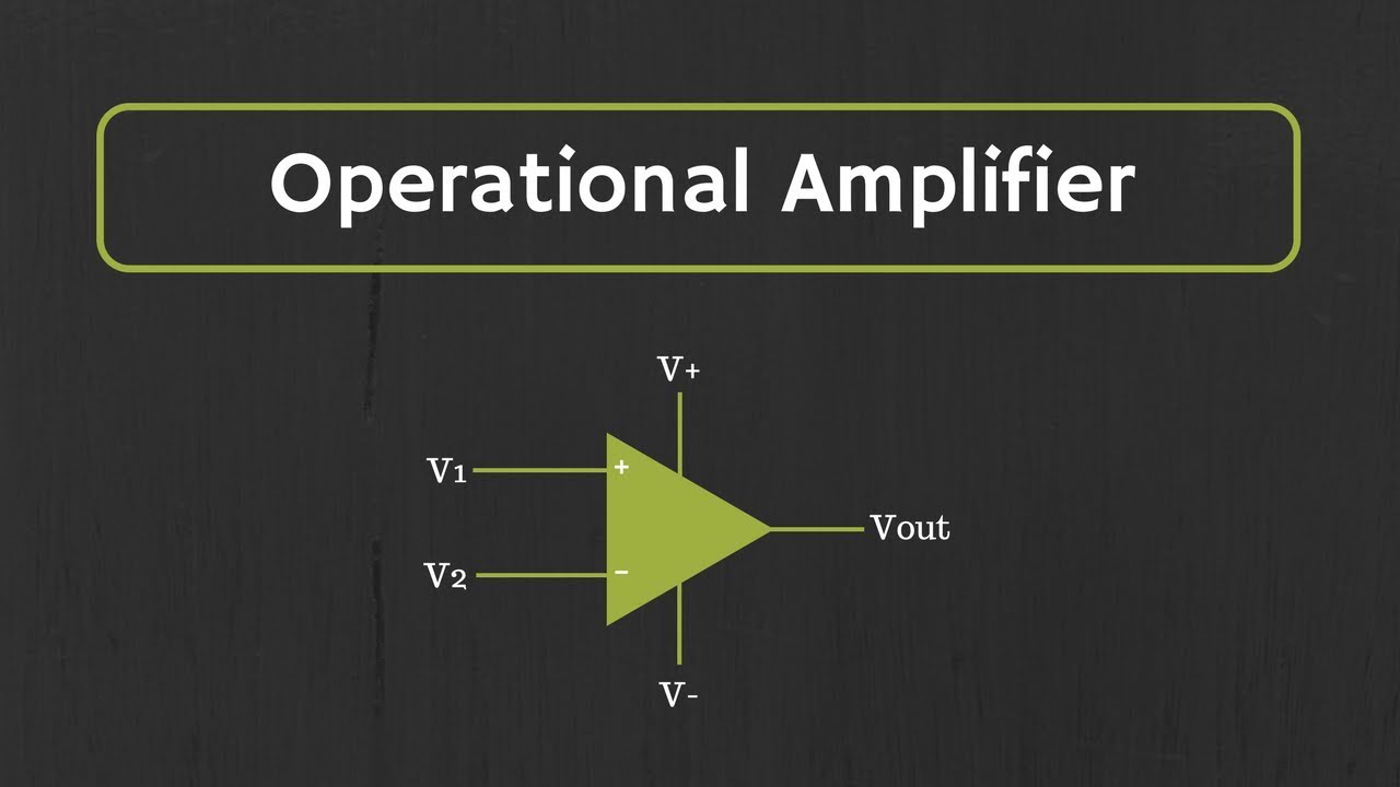
- 😀 The video discusses how to design a current to voltage converter using an operational amplifier (op-amp).
- 🔌 Current to voltage converters are useful in applications where a sensor or circuit component outputs current, such as photodiodes.
- 📈 These converters are essential for logging data from current-output devices using data acquisition systems that require voltage input.
- 🔗 The basic principle involves converting the input current into an output voltage, which is achieved by controlling the input current to manipulate the output voltage.
- 🔍 A simple passive circuit using a resistor can be used for current to voltage conversion, but it has limitations due to load resistance affecting the output voltage.
- 🚫 The passive converter's output voltage depends on the load resistance, which is not ideal for applications requiring an independent output voltage.
- 🔌 An active converter using an op-amp can overcome this issue by maintaining a consistent output voltage independent of the load resistance.
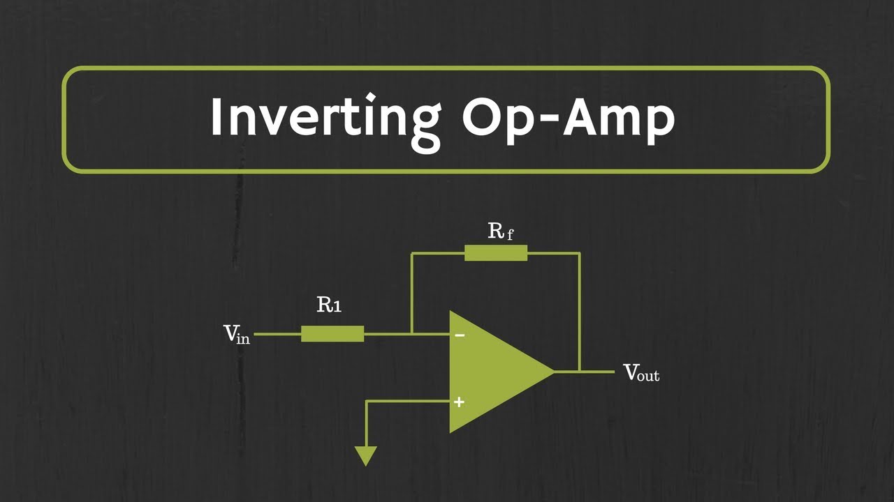
- 💡 The op-amp-based converter uses the inverting terminal for input current and a feedback resistor between the output and inverting terminal to achieve the conversion.
- 🌞 The video provides an example of using the converter with a photodiode, where the photocurrent is converted into a voltage proportional to the light intensity.
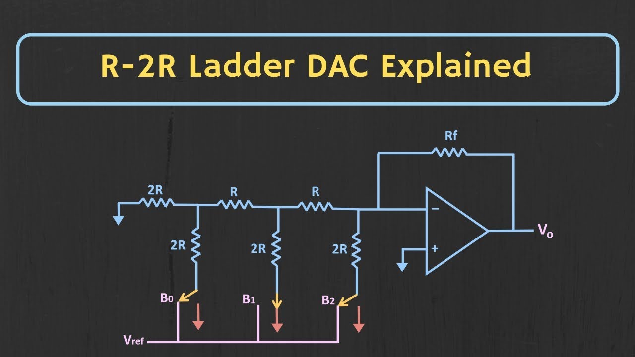
- 🔢 The converter is also applicable in digital to analog converters (DACs), where digital input bits are converted into an analog output voltage based on the current through resistors.
- 📚 The script concludes with an invitation for viewers to ask questions or provide feedback in the comments and encourages engagement through likes and subscriptions.
Q & A
What is the purpose of a current to voltage converter?
-A current to voltage converter is used to convert an input current into an output voltage. This is useful in applications where a sensor or circuit component outputs data in terms of current, and the data acquisition system requires voltage input.
Why are current to voltage converters important in data logging scenarios?
-Current to voltage converters are important in data logging scenarios because they allow the conversion of current outputs from sensors like photodiodes into voltage, which can be logged and monitored over time using data acquisition systems that typically accept voltage inputs.
What is a limitation of passive current to voltage converters?
-A limitation of passive current to voltage converters is that the voltage across the load depends on the load resistance. This means that the converted voltage is not independent of the load resistance, leading to potential inaccuracies in the output voltage.
How does an active current to voltage converter overcome the limitations of passive converters?
-An active current to voltage converter, typically using an operational amplifier (op-amp), overcomes the limitations of passive converters by maintaining the output voltage independent of the load resistance. This is achieved by using the op-amp's inverting terminal and feedback resistor to control the output voltage based on the input current.
What is the role of the feedback resistor in an op-amp based current to voltage converter?
-The feedback resistor in an op-amp based current to voltage converter is crucial as it determines the output voltage. The output voltage is proportional to the input current multiplied by the value of the feedback resistor, ensuring that the output voltage is independent of the load resistance.
What is the term used to describe the ratio of output voltage to input current in a current to voltage converter?
-The ratio of output voltage to input current in a current to voltage converter is described as transimpedance. This term is used because the ratio has the unit of impedance, reflecting the relationship between current and voltage in the converter.
How can a current to voltage converter be used in photodiode circuits?
-In photodiode circuits, a current to voltage converter can be used to convert the photocurrent generated by the photodiode, which varies with light intensity, into a proportional voltage output. This allows for the measurement and monitoring of light intensity through voltage readings.
What is the significance of the virtual ground concept in op-amp based circuits?
-The virtual ground concept in op-amp based circuits is significant because it allows the inverting terminal of the op-amp to be at zero voltage, which is crucial for maintaining the desired circuit operation. This concept ensures that the input current is accurately converted into the output voltage without being affected by the load resistance.
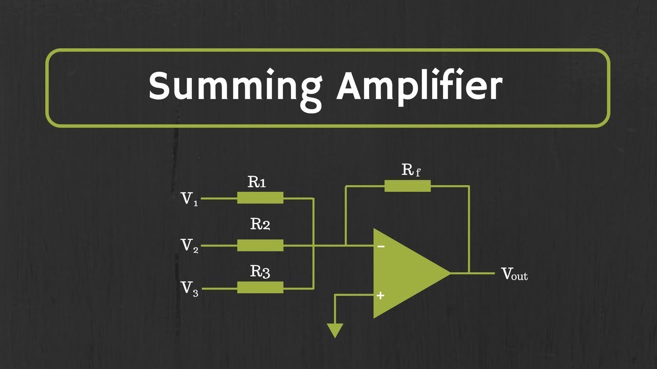
How does a current to voltage converter work in a digital to analog converter (DAC)?
-In a digital to analog converter, a current to voltage converter is used to convert digital data bits into an analog output voltage. Each bit is treated as a current source, and the total current flowing through a feedback resistor determines the output voltage. The output voltage is proportional to the sum of the currents corresponding to the digital input bits.
What are some applications of current to voltage converters beyond photodiode circuits?
-Beyond photodiode circuits, current to voltage converters are used in various applications such as in digital to analog converters, where they help convert digital data into an analog output voltage. They can also be used in sensor data acquisition systems, where they convert sensor outputs in current form into a voltage form that can be easily measured and recorded.
Outlines

This section is available to paid users only. Please upgrade to access this part.
Upgrade NowMindmap

This section is available to paid users only. Please upgrade to access this part.
Upgrade NowKeywords

This section is available to paid users only. Please upgrade to access this part.
Upgrade NowHighlights

This section is available to paid users only. Please upgrade to access this part.
Upgrade NowTranscripts

This section is available to paid users only. Please upgrade to access this part.
Upgrade NowBrowse More Related Video
Operational Amplifier: Inverting Op Amp and The Concept of Virtual Ground in Op Amp
Op-Amp: Summing Amplifier (Inverting and Non-Inverting Summing Amplifiers)

Operational Amplifier: Op-Amp as Differential Amplifier or Op-Amp as subtractor (With Examples)
Introduction to Operational Amplifier: Characteristics of Ideal Op-Amp
R-2R Ladder DAC Explained (with Solved Example)

How does Buck Converter work? | DC-DC Converter - 1
5.0 / 5 (0 votes)