Operational Amplifier: Inverting Op Amp and The Concept of Virtual Ground in Op Amp
Summary
TLDRThis video from 'All About Electronics' YouTube channel delves into the inverting input configuration of an operational amplifier (op-amp), highlighting the concept of virtual ground. It explains how op-amps, with their high gain, can be used as amplifiers in their linear region by applying negative feedback. The video illustrates how to control op-amp gain using feedback resistors and introduces the virtual ground concept, which is crucial for understanding inverting op-amp configurations. Practical examples show how to calculate gain and phase inversion, making the content both informative and engaging.
Takeaways
- π¬ The video discusses the inverting input configuration of an operational amplifier (Op-Amp) and introduces the concept of virtual ground.
- π Op-Amps are high-gain differential amplifiers with gains typically ranging from 10^5 to 10^6.
- π Even a small differential input voltage can saturate the output of an Op-Amp due to its high gain.
- π The video explains that to use an Op-Amp as a linear amplifier, it must operate within its linear region, not at saturation.
- π Feedback control is necessary to manage the high gain of an Op-Amp, and this can be achieved by feeding output back to the input.
- β Positive feedback, where output is fed back to the non-inverting input, can lead to instability and is not recommended.
- β Negative feedback, where output is fed back to the inverting input, is used to control the Op-Amp's gain and ensure stability.
- π© The inverting configuration of an Op-Amp is achieved by applying input to the inverting input terminal and grounding the non-inverting terminal.
- π‘ The concept of virtual ground arises when negative feedback is applied, making the inverting and non-inverting inputs nearly equal in potential.
- βοΈ The gain of the inverting Op-Amp configuration can be calculated and controlled using the values of resistors Rf (feedback resistor) and R1 (input resistor).
- π The output voltage of the inverting Op-Amp configuration is 180 degrees out of phase with the input voltage, resulting in an inverted signal.
Q & A
What is the main topic of the video?
-The main topic of the video is the inverting input configuration of an operational amplifier (op-amp) and the concept of virtual ground.
What is an operational amplifier?
-An operational amplifier, or op-amp, is a high-gain differential amplifier used in various applications due to its high input impedance and low output impedance.
What is the typical gain range of an op-amp?
-The typical gain range of an op-amp is between 10^5 to 10^6.
Why is it important to use an op-amp in its linear region?
-It is important to use an op-amp in its linear region to ensure a linear relationship between input and output, which is necessary for accurate amplification.
What is the purpose of feedback in an op-amp circuit?
-Feedback in an op-amp circuit is used to control the gain of the amplifier and to ensure it operates within its linear region.
What are the two types of feedback that can be applied to an op-amp?
-The two types of feedback that can be applied to an op-amp are positive feedback and negative feedback.
Why is positive feedback not used alone in op-amp circuits?
-Positive feedback is not used alone because it can lead to instability in the system.
How does negative feedback help in controlling the gain of an op-amp?
-Negative feedback helps in controlling the gain of an op-amp by feeding a fraction of the output voltage back to the inverting input terminal.
What is a virtual ground?
-A virtual ground is a concept in op-amp circuits where the inverting and non-inverting input terminals are at the same potential, even though they are not physically connected.
How does the virtual ground affect the input voltages in an inverting op-amp configuration?
-In an inverting op-amp configuration, the virtual ground concept implies that the voltage at the inverting input terminal is nearly equal to the voltage at the non-inverting input terminal, which is grounded.
How is the closed-loop gain of an inverting op-amp configuration calculated?
-The closed-loop gain of an inverting op-amp configuration is calculated using the relationship Vout/Vin = -Rf/R1, where Rf is the feedback resistor and R1 is the input resistor.
What does the negative sign in the closed-loop gain formula indicate?
-The negative sign in the closed-loop gain formula indicates that the output voltage is 180 degrees out of phase with respect to the input voltage.
How can the gain of an op-amp be controlled using the inverting configuration?
-The gain of an op-amp in an inverting configuration can be controlled by adjusting the values of the feedback resistor (Rf) and the input resistor (R1).
Outlines
π¬ Introduction to Inverting Op-Amp Configuration
This paragraph introduces the concept of the inverting input configuration of an operational amplifier (op-amp). It discusses the high gain differential nature of op-amps, typically ranging from 10^5 to 10^6. The video explains that even a very small differential input voltage can saturate the output due to this high gain. The importance of operating within the linear region for amplification is highlighted, and the necessity of controlling the op-amp's gain through feedback is introduced. The paragraph distinguishes between positive and negative feedback, noting that positive feedback can lead to instability and is not used alone. The focus then shifts to negative feedback, which is achieved by feeding a fraction of the output voltage to the inverting input terminal. Three methods of applying input to the op-amp are outlined: through the non-inverting input terminal, through the inverting input terminal, and through both terminals simultaneously. The paragraph concludes by setting the stage for a detailed explanation of the inverting configuration, where input is applied to the inverting input terminal.
π The Concept of Virtual Ground in Op-Amp
The second paragraph delves into the concept of virtual ground in the context of op-amps with negative feedback. It begins by establishing that a differential input voltage of 10 microvolts can saturate the op-amp, suggesting that the voltage difference between the inverting and non-inverting inputs is minimal. This leads to the concept of virtual ground, where the inverting input terminal acts as if it were grounded despite not being physically connected to ground. The virtual ground concept is crucial for understanding how the op-amp operates in the inverting configuration. The paragraph then uses Ohm's law to derive the relationship between the output voltage (Vout) and the input voltage (Vin) in terms of the feedback resistor (Rf) and the input resistor (R1). The resulting equation, Vout/Vin = -Rf/R1, reveals how the gain of the op-amp can be controlled by adjusting Rf and R1. The paragraph concludes with an example demonstrating how changing these resistor values can alter the gain and phase of the output signal relative to the input signal, emphasizing the utility of the inverting op-amp configuration for amplification purposes.
Mindmap
Keywords
π‘Operational Amplifier
π‘Inverting Input Configuration
π‘Virtual Ground
π‘Open-Loop Gain
π‘Feedback
π‘Non-Inverting Input Terminal
π‘Differential Input Voltage
π‘Saturation Voltage
π‘Resistor
π‘Closed-Loop Gain
π‘Phase Inversion
Highlights
Introduction to the inverting input configuration of the operational amplifier.
Explanation of the concept of virtual ground in Op-Amp.
Op-Amp is a high gain differential amplifier with a gain range of 10^5 to 10^6.
Saturation occurs at small differential input voltages due to the high gain.
The importance of using Op-Amp in the linear region for amplification.
Controlling the gain of the Op-Amp using feedback from the output.
Two ways to apply feedback: to the non-inverting or inverting input terminals.
Positive feedback leads to system instability and cannot be used alone.
Negative feedback is used to control the gain of the Op-Amp.
Three ways to apply input to the Op-Amp: non-inverting, inverting, or both terminals.
Inverting input configuration where input is applied to the inverting terminal.
Derivation of the relationship between output and input voltages in an inverting configuration.
The concept of virtual ground when negative feedback is applied.
Virtual ground means the inverting and non-inverting inputs are at the same potential.
Derivation of the closed-loop gain expression for the inverting Op-Amp configuration.
Controlling the gain of the Op-Amp by changing the values of Rf and R1.
The output voltage is 180 degrees out of phase with the input voltage.
Practical example of controlling gain with specific resistor values.
Summary of the inverting Op-Amp configuration and virtual ground concept.
Transcripts
Hey friends, Welcome to the YouTube channel ALL ABOUT ELECTRONICS.
So, in this video, we are going to talk about the inverting input configuration of the operational
amplifier and we will see the concept of virtual ground in the Op-Amp.
Now, in the last video, we have seen the basics of this operational amplifier and we had seen
that this op-amp is a very high gain differential amplifier.
And the gain of the op-amp used to be in the range of 10 to the power 5 to the 10 to the
power 6.
And we had seen that even if apply a very small amount of differential input voltage
between the input terminals of the op-amp, then also the output will be get saturated
towards the biasing points.
And then we had seen the voltage transfer curve of this op-amp.
And then we had seen that even if we apply the small input voltage to this op-amp then
also the output will be get saturated either towards the positive or the negative saturation
voltages.
Now, let's say the saturation voltage for the op-amp is 10V, and the open loop gain
of this opamp is let's say 10 to the power 6.
So, this op-amp will get saturated at 10 microvolts of a differential input voltage.
So, now whenever we want to use this op-amp as an amplifier, we need to use it in the
linear region.
That means in this region.
So, that the input and output have a linear relationship.
But whenever we are using this op-amp in open loop configuration, then this linear range
is very small.
So, if we want to use this op-amp as an amplifier, then we need to somehow control the gain of
this amplifier.
And we can do so, by applying the feedback from output to the input side.
So, there are two ways, by which we can apply this feedback.
One is providing feedback from output to this positive input terminal.
Or let's say non-inverting input terminal.
And the second is providing the feedback from output to this inverting input terminal.
Now, whenever we are providing the feedback from this output to this non-inverting input
then that kind of feedback is known as the positive feedback.
Because here the fraction of an output voltage is getting added to this non-inverting input.
Now, whenever in any system we are using the positive feedback, then this positive feedback
leads that system to the instability.
So, we can not use this positive feedback alone.
So now here to control the gain of the op-amp, we need to go for this negative feedback.
That means we need to feed the fraction of the output voltage to this inverting input
terminal.
Now, here three ways by which we can apply the input to this op-amp.
The first is applying the input to this non-inverting input terminal and grounding this negative
input terminal.
Second is providing the input to this inverting input terminal and grounding this positive
terminal.
And third is providing the input to both non-inverting as well as inverting input terminals.
So, first, we will see the case when we are applying the input to this inverting input
terminal.
So, let's say we have applied input to this inverting input terminal through one resistor
R1.
And we are providing negative feedback from output to this inverting input terminal via
this feedback resistor Rf.
So, now whenever op-amp is used in this configuration then this configuration is known as the inverting
op-amp configuration.
So, now in this configuration let's find out the relationship between this output and the
input voltages.
And let's see how we can control the gain of op-amp by using this feedback resistor
Rf and this resistor R1.
So, let's find the relationship between this output and input in terms of this feedback
resistor Rf and R1.
So, now before we derive this expression, let's understand the concept of virtual ground
in the op-amp.
And this concept of virtual ground is applicable when we are providing the negative feedback
to this op-amp.
Now, let's say for the given op-amp the open-loop gain of this op-amp is 10 to the power 6.
And we know that the output voltage Vout of op-amp can be given as A times the differential
input voltage.
That is the input voltage between these inverting and the non-inverting input terminals.
Now, here let's assume that through this negative feedback we are controlling the output voltage
of this op-amp in as such way that the output voltage is always less than the saturation
voltage.
Or we can say that we are operating this op-amp in a linear region.
So, let's assume that the output voltage is 10 V.
So, we can say that 10V that is equal to 10 to the power 6 times this differential input
voltage.
Or we can say that the differential input voltage is equal to 10 microvolts.
Now, here this differential input voltage is nothing but the difference between this
inverting and the non-inverting input terminals.
So, we can write this differential input voltage as (Vplus ) - (Vminus)
that is equal to 10 microvolts.
Now, here this 10 microvolts is very small signal and we can almost neglect it.
So, we can write this (Vplus) - (Vminus) as approximately equal to zero volts.
Or we can say that Vplus that is equal to Vminus.
It means that the inverting and the non-inverting input terminals are at the same potential.
Or we can say that there is virtual short between this inverting and the non-inverting
input terminals.
Now, here the term virtual means that these two terminals are not actually short-circuited
but they are virtually short-circuited.
So, whatever voltage that appears at one terminal, the exact same voltage will appear at another
terminal.
So, now in this configuration, this non-inverting input terminal is grounded.
So, we can say that Vplus that is equal to zero.
So, according to this conclusion, Vminus should be equal to zero.
It means that this terminal is not actually grounded but it will act as a virtual ground.
So, this negative feedback will ensure that the difference between this inverting and
the non-inverting input is very small or we can say that it is almost negligible.
And because of that, we can consider these both input terminals at the same potential.
So, this concept is known as the virtual ground concept.
So, now let's use this concept if virtual ground and let's derive the expression between
this Vout and Vin.
Now, here let's say the current I1 is the current that is flowing through this resistor
R1.
And let's say this node is node X.
And let's say the current that is flowing through this resistor Rf is If.
Now, in the last video, we had seen that the op-amp has very high input impedance.
Or if we consider the ideal op-amp then the input impedance of the op-amp is infinite.
It means that no current is entering into this op-amp.
Or we can say that current I that is equal to zero.
It means that I1 is equal to If.
So, now we can write this I1 as, Vin minus Vx, divide by R1.
Where Vx is the voltage at this particular node.
Likewise, we can write this current If as Vx minus Vout, divide by Rf.
Now, if we apply the concept of virtual ground, then this node x should have zero potential.
Because this non-inverting input terminal is grounded.
So, the value of Vx should be equal to zero.
So, we can write this expression as Vin divide by R1 that is equal to minus Vout divide by
Rf. and if we rearrange it then we can write it
as Vout by Vin, that is equal to minus Rf divide by R1.
And this expression is known as the closed loop gain for this inverting op-amp configuration.
So, as you can see here, just by changing the value of this Rf and R1 we can control
the gain of this op-amp.
And we can use this op-amp as an amplifier.
Now, here the negative sign indicates that the output voltage is 180 degree out of phase
with respect to input voltage.
So, let's say, if we have applied the sinusoidal signal at the input, then at the output we
will get the amplified sinusoidal signal which is having a 180-degree phase with respect
to the input signal.
And that is why this configuration of the op-amp is known as the inverting configuration.
Because the output will be get inverted with respect to input voltage.
So, let's say in this case if Rf is equal to 2 kilo-ohms and R1 is equal to 1 kilo-ohm,
then the gain of the op-amp will be equal to 2. and suppose if we apply the 1 volt of
a signal, then at the output we will get 2V of a signal which is 180 degree out of phase
with respect to 1V signal.
So, in this way, by controlling the value of Rf and R1, we can control the gain of this
op-amp and we can use this op-amp as an amplifier.
So, I hope in this video, you understood the inverting op-amp configuration and the concept
of virtual ground.
So, if you have any question or suggestion do let me know in the comment section below.
If you like this video, hit the like button and subscribe to the channel for more such
videos.
Browse More Related Video
Operational Amplifiers - Inverting & Non Inverting Op-Amps
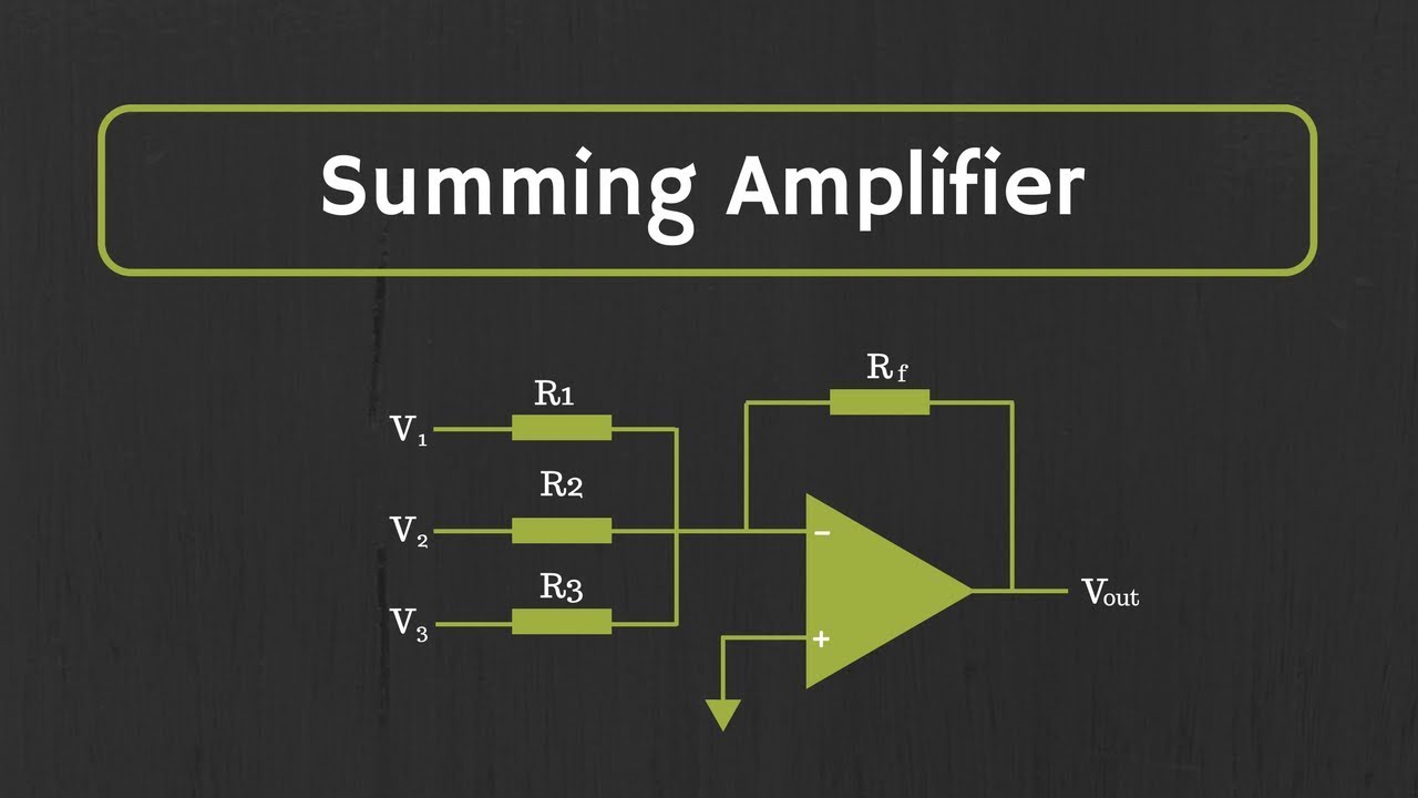
Op-Amp: Summing Amplifier (Inverting and Non-Inverting Summing Amplifiers)
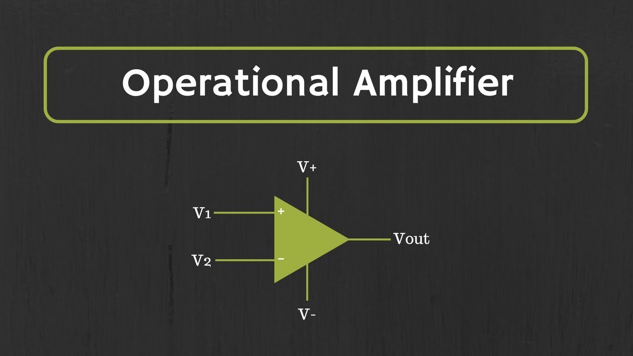
Introduction to Operational Amplifier: Characteristics of Ideal Op-Amp
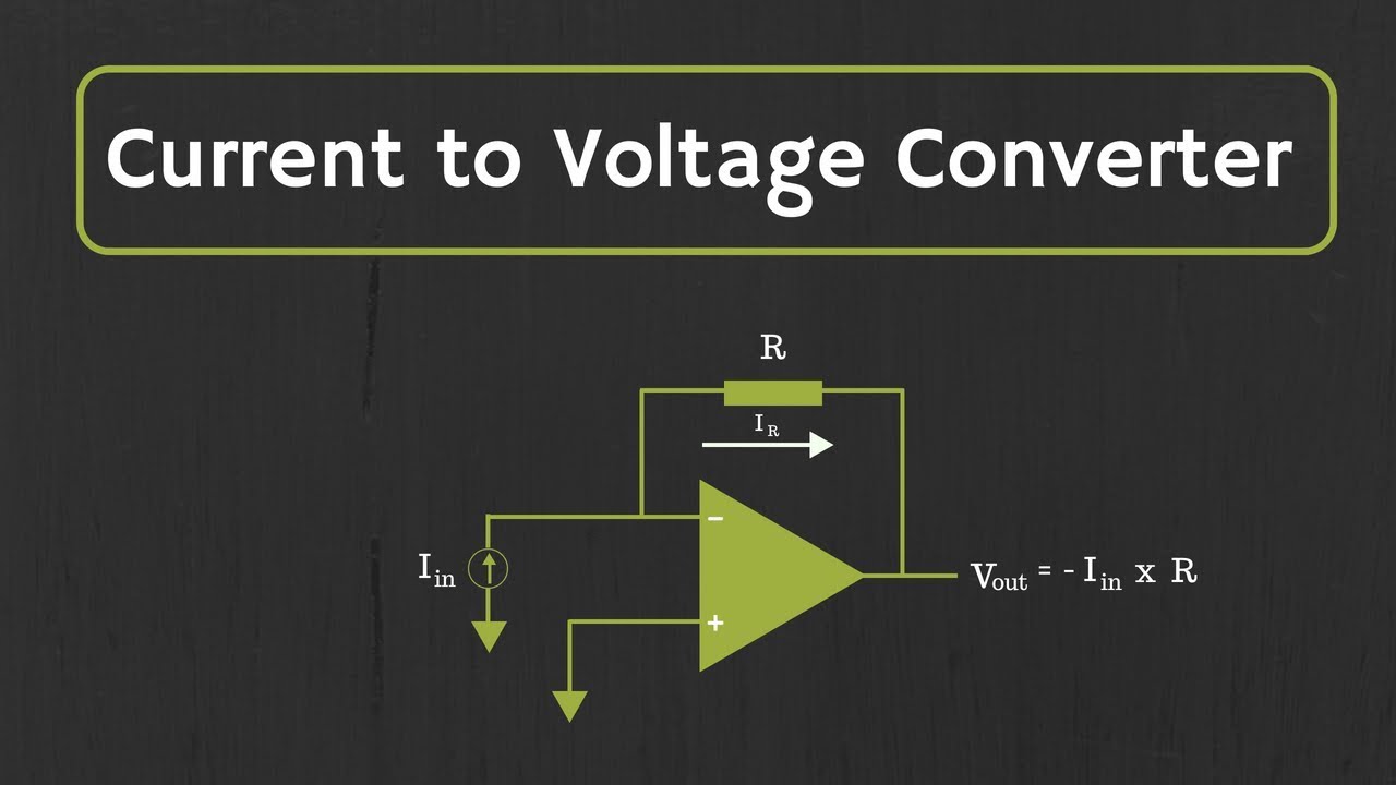
What is an operational amplifier?
Electronic Basics #21: OpAmp (Operational Amplifier)
Active Low Pass Filter and Active High Pass Filter Explained
5.0 / 5 (0 votes)