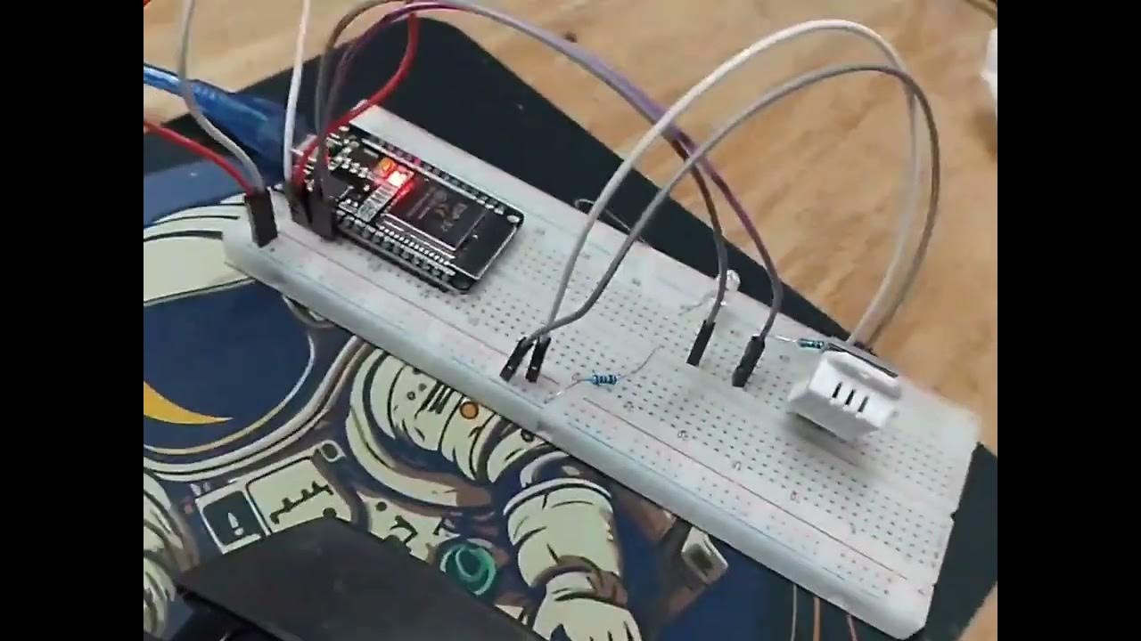
New Blynk IOT Smart Plant Monitoring System

Viral Science - The home of Creativity
31 Dec 202216:54

Summary

TLDRIn this tutorial, the creator unveils a smart plant monitoring system integrated with the Blink IoT platform, featuring real-time data access via a smartphone app and web dashboard. The project utilizes sensors like PIR motion, DHT11 for temperature and humidity, and a soil moisture sensor, controlled by an ESP8266 board. It also includes a relay module for a water pump and an LCD display for sensor readings. The video guides through the assembly, Blink IoT platform setup, and code uploading, showcasing a hands-on approach to home gardening tech.

Takeaways

  • 🌟 The video is sponsored by LTM 365, a PCB designing tool, and Octopart, a search engine for electronic components.
  • 🎉 The presenter wishes viewers a Happy New Year and introduces a smart plant monitoring system project.
  • 🌱 The smart plant monitoring system is an upgraded version that works with the Blink IoT platform and can be controlled via a smartphone app or web dashboard.
  • 📱 The system includes sensors for PIR motion, temperature, humidity, and soil moisture, along with a relay module to control a water pump or DC motor.
  • 💧 A 16x2 I2C LCD display is used to show real-time data from the sensors, including temperature, humidity, soil moisture, motion detection, and water pump status.
  • 🔌 The project is powered by an ESP8266 board and includes a manual button for the water pump with real-time feedback on the application.
  • 🛠️ The required components for the project are listed, including the ESP8266 board, sensors, a relay module, a display, a push button, a water pump, and a 7.4V 18650 battery.
  • 🔗 Links for free trials of Altium Designer, LTM 365, and Octopart are provided in the video description for interested viewers.
  • 🛑 The video demonstrates how to set up the project on the Blink IoT platform, including creating data streams, events, and configuring the web dashboard and mobile application.
  • 🔧 The presenter guides viewers through the process of connecting the sensors and components to the ESP8266 board according to a provided circuit diagram.
  • 📲 The video concludes with a demonstration of the smart plant monitoring system in action, showing real-time data on the LCD display, mobile app, and web dashboard.

Q & A

  • What is the main focus of the video?

    -The video focuses on demonstrating how to make a smart plant monitoring system that works with the Blink IoT platform.

  • What is the purpose of the PIR motion sensor in this project?

    -The PIR motion sensor is used to detect any animal activity in the vicinity of the plant.

  • Which temperature and humidity sensor is used in the project?

    -A DHT11 temperature and humidity sensor is used in the smart plant monitoring system.

  • What does the soil moisture sensor do in the project?

    -The soil moisture sensor is used to measure the moisture level in the soil to determine when the plant needs watering.

  • How is the water pump controlled in the project?

    -A relay module is used to turn the water pump on and off, which is demonstrated with a DC motor in the project.

  • What display is used to show sensor values in the project?

    -A 16x2 I2C LCD display is used to display values from the sensors, such as temperature, humidity, and soil moisture.

  • What platform does the smart plant monitoring system communicate with?

    -The system communicates with the Blink IoT platform, allowing for real-time monitoring and control via smartphone and web dashboard.

  • How can viewers access the codes and circuit diagram for the project?

    -The codes and circuit diagram can be downloaded from the website link provided in the video description.

  • What is the role of the push button in the project?

    -The push button is used to manually turn the water pump on and off, providing real-time feedback on the application.

  • What is the significance of the Blink IoT application in the project?

    -The Blink IoT application allows users to view real-time data from the sensors and control the water pump and PIR sensor remotely.

  • How does the project notify the user of motion detection?

    -When motion is detected by the PIR sensor, the user receives a notification on their smartphone, and a red light glows on the application indicating motion.

Outlines

00:00

🌱 Smart Plant Monitoring System Introduction

This paragraph introduces a sponsored video about a smart plant monitoring system project. The project integrates with the Blink IoT platform and includes upgrades from previous versions. The system uses various sensors such as a PIR motion sensor, DHT11 for temperature and humidity, and a soil moisture sensor. Additionally, a relay module controls a water pump, and a 16x2 I2C LCD display shows sensor data. Viewers can download the code and circuit diagram from the provided website link. The project is demonstrated to work with a smartphone application and a web dashboard, offering real-time data and control over the system.

05:01

🛠️ Setting Up the Smart Plant Monitoring System

This section details the components and setup process for the smart plant monitoring system. It lists the required materials, including an ESP8266 NodeMCU board, sensors, a relay module, a push button, a water pump, and a battery. The video script guides viewers through connecting the sensors to the NodeMCU board, setting up data streams on the Blink IoT platform, and creating events for notifications. It also explains how to configure the web dashboard with gauges, switches, and an LED indicator for motion detection.

10:03

📱 Mobile Application and Real-Time Data Visualization

The paragraph explains how to configure the mobile application for the smart plant monitoring system. It describes adding widgets to the mobile dashboard that mirror those on the web dashboard, including gauges for temperature, humidity, and soil moisture, as well as switches for the PIR motion sensor and water pump control. The LED indicator is also configured to show motion detection. The video demonstrates real-time data visualization on the mobile application and the web dashboard, emphasizing the system's interactivity and remote monitoring capabilities.

15:04

🎥 Demonstration and Conclusion of the Smart Plant Monitoring System

The final paragraph showcases a live demonstration of the smart plant monitoring system. It illustrates how the sensors respond to environmental changes and user interactions, such as turning the motion sensor on and off, testing the soil moisture sensor with water, and manually controlling the water pump. The video concludes with a call to action, encouraging viewers to like, share, and subscribe for more content, and to enable notifications for new video releases.

Mindmap

Keywords

💡PCB Designing Tool

A PCB (Printed Circuit Board) designing tool is software used to plan and create the layout of electronic circuits. In the video, LTM 365 is mentioned as a very good PCB designing tool, highlighting its features that make the design process easy and fast. It allows for collaboration by sharing designs with team members who can then view and comment on the designs using a web browser.

💡Search Engine for Electronic Components

This refers to a specialized search engine like OctoPart, which is used to find detailed information about electronic components. The video mentions OctoPart as being linked with LTM 365, providing real-time insights and data about components, which is essential for electronic projects and making informed decisions about what components to use.

💡Smart Plant Monitoring System

The main theme of the video is the Smart Plant Monitoring System, a project that uses various sensors and an IoT platform to monitor and manage plant health. The system includes sensors for detecting temperature, humidity, soil moisture, and motion, and can control a water pump to provide water to the plants as needed. It demonstrates the application of IoT in home gardening and agriculture.

💡Blink IoT Platform

Blink IoT platform is the central system used in the Smart Plant Monitoring System project. It is responsible for receiving data from the sensors, processing it, and displaying it on both a web dashboard and a mobile application. The platform allows for real-time monitoring and control of the plant's environment, as shown in the video.

💡Sensors

Sensors are devices that detect and respond to some type of input from the environment. In the context of the video, several types of sensors are used: a PIR motion sensor for animal activity, a DHT11 for temperature and humidity, and a soil moisture sensor. These sensors are integral to the Smart Plant Monitoring System, providing data that helps maintain optimal conditions for plant growth.

💡Relay Module

A relay module is an electronic device that is used to control a high voltage or high current device with a low voltage signal. In the video, a relay module is used to control the water pump, turning it on and off based on the readings from the soil moisture sensor. This is an example of how electronics can automate tasks in a smart system.

💡I2C LCD Display

An I2C LCD Display is a type of liquid crystal display that communicates with a microcontroller using the Inter-Integrated Circuit (I2C) protocol. In the video, a 16x2 I2C LCD display is used to show real-time values from the sensors, such as temperature, humidity, and soil moisture levels, providing a visual interface for the Smart Plant Monitoring System.

💡ESP8266 Board

The ESP8266 is a microcontroller board that is widely used in IoT projects for its Wi-Fi capabilities. In the script, the ESP8266 board is the central processing unit of the Smart Plant Monitoring System, running the code that communicates with the Blink IoT platform and controls the system's functions.

💡Data Streams

Data streams in the context of the Blink IoT platform refer to the continuous flow of data from the sensors to the platform. The video describes creating data streams for temperature, humidity, soil moisture, water pump status, and PIR motion sensor, which are essential for the platform to display and react to the sensor data.

💡Events

In the Blink IoT platform, events are triggers based on certain conditions, such as motion detection. The video script describes setting up an event for the PIR motion sensor that sends a warning message and triggers notifications to the device owner when motion is detected, demonstrating how the system can alert users to important changes.

💡Mobile Application Dashboard

The mobile application dashboard is the user interface of the Blink IoT platform on a smartphone. The video script explains how to configure this dashboard with widgets for temperature, humidity, soil moisture, and control buttons for the PIR sensor and water pump, as well as an LED indicator for motion detection, allowing users to monitor and control the Smart Plant Monitoring System on the go.

Highlights

Introduction of a smart plant monitoring system project with upgrades for the new Blink IoT platform.

The project allows monitoring of plant conditions through a smartphone app and web dashboard.

Use of PIR motion sensor for detecting animal activity around the plant.

Inclusion of a DHT11 temperature and humidity sensor for environmental monitoring.

Utilization of a soil moisture sensor to assess the plant's watering needs.

Demonstration of a relay module to control a water pump or DC motor for watering.

Introduction of a 16x2 I2C LCD display for real-time sensor data visualization.

The system operates with an ESP8266 board for IoT connectivity.

Manual control of the water pump with real-time feedback on the application.

Mobile application features for viewing temperature, humidity, and soil moisture data.

Ability to receive notifications and view motion activity alerts on the smartphone.

Components list provided for replicating the smart plant monitoring system.

Step-by-step guide on connecting the circuit according to a provided diagram.

Use of the 365 Designer tool for efficient PCB designing with team collaboration features.

Integration of Octopart for real-time electronic component data and insights.

Instructions on setting up the Blink IoT platform for data streaming and event management.

Creating a web dashboard with gauges, switches, and LEDs for visual control.

Mobile application setup for real-time monitoring and control of the plant system.

Uploading and configuring the code for the ESP8266 board to interact with Blink IoT.

Live demonstration of the smart plant monitoring system in action.

Testing of individual sensors and their real-time feedback on the application.

Conclusion and call to action for likes, shares, and subscriptions for more project videos.

Transcripts

play00:01

viral science the home of creativity

play00:05

this video is sponsored by LTM 365. it's

play00:08

a very good PCB designing tool and

play00:10

octopath which is a very good and fast

play00:12

search engine for electronic components

play00:15

hey friends welcome back to another

play00:16

video and wish you all a very happy New

play00:18

Year I hope everyone is good and you're

play00:21

watching me after a very long time so

play00:23

here I am and in this video I'll show

play00:25

you how to make this smart plant

play00:26

monitoring system so this is a project

play00:28

which I have made few years ago but now

play00:31

this one has little more upgrades and

play00:33

this works with the new blink iot

play00:35

platform so this was the request from

play00:37

many of my subscribers so here is the

play00:39

project and you can download the codes

play00:41

and circuit diagram from the website

play00:44

link will be in the description down

play00:45

below so let's get started with this

play00:47

video

play00:49

so here is our project Smart Plan

play00:50

monitoring system which works with the

play00:52

new blink iot platform

play00:54

and over here you can find all the data

play00:57

on the smartphone as well it's the blink

play01:00

application and even you can view the

play01:02

same thing on the web dashboard as well

play01:04

so the sensors we have used is the PIR

play01:06

motion sensor for any animal activity

play01:10

then we are using a DHT 11 temperature

play01:12

humidity sensor

play01:14

then we have a soil moisture sensor

play01:19

next we are using a relay module to turn

play01:22

on and off a water pump

play01:24

so instead of water pump I've connected

play01:26

a DC motor just to demonstrate the water

play01:28

pump then we are using a battery to

play01:30

power the water pump

play01:33

and then we are using a 16 to 2 i2c LCD

play01:36

display to display all the values from

play01:38

the sensors so we can see temperature

play01:40

humidity soil moisture motion detection

play01:42

and water pump

play01:46

so this was the complete project and it

play01:49

runs with esp8266 board

play01:52

and you will also find a water pump

play01:54

button to turn on and off the water pump

play01:57

manually

play01:58

this button also gives the real-time

play02:01

feedback on the application as well

play02:03

so that was the complete project

play02:07

now in the mobile application you can

play02:09

see the data of temperature humidity

play02:11

soil moisture and you will find button

play02:13

to turn on and off PIR sensor

play02:16

so when I turn it on and if any motion

play02:18

activity detects then you will get a

play02:21

notification on your smartphone and even

play02:23

a red light glows on the application it

play02:26

states that some motion is been

play02:28

conducted

play02:30

next you will find a button to turn on

play02:33

and off the water pump

play02:36

so to make this project you will need a

play02:38

esp2266 nodemc board

play02:41

this is dht11 temperature and humidity

play02:44

sensor

play02:46

this is a PIR motion sensor

play02:50

this is soil moisture sensor

play02:54

then you'll need a relay module

play02:57

[Music]

play02:58

this is 16 into 2 i2c display

play03:04

a push button

play03:10

a water pump

play03:12

breadboard

play03:16

this is 7.4 volt 18650 battery and

play03:20

you'll also need some jumpers

play03:23

now follow the circuit diagram and make

play03:25

your connections

play03:26

so first we will be connecting all the

play03:28

grounds from all the sensors to the node

play03:31

MCU board

play03:32

foreign

play03:36

[Music]

play03:41

next we'll connect all the positive

play03:43

power connections to 3.3 volt

play03:47

and the relay will be connecting to the

play03:49

vi and pin so we can directly get the 5

play03:52

volt power from the USB

play03:57

[Music]

play04:01

and now we'll proceed with the rest of

play04:03

the digital pin connections and analog

play04:06

pin connections

play04:10

foreign

play04:23

[Music]

play04:43

365 designer is amazing tool with lots

play04:47

of features that makes PCB designing

play04:49

very easy and fast you can share your

play04:52

PCB designs with a click to your

play04:54

teammate and they will receive an email

play04:56

with the link where they can easily view

play04:58

the designs using the browser and

play05:00

comment the reviews and Corrections on

play05:02

the project itself

play05:04

LTM 365 is a full build package and

play05:07

requires no additional licenses

play05:10

and with the octopart linked with LTM

play05:12

you can get real-time insights and the

play05:14

data of all the components it's the fast

play05:17

search engine for electronic components

play05:19

and you can find each minute detail of

play05:22

the components in it

play05:23

[Music]

play05:26

links for the free trial Altium designer

play05:28

LTM 365 and octopart is in the

play05:31

description below so you can check it

play05:32

out

play05:33

so now step by step we'll do the

play05:35

connections according to the circuit

play05:37

diagram which we created

play05:40

[Music]

play05:41

foreign

play05:44

[Music]

play05:53

[Music]

play06:03

[Music]

play06:09

[Music]

play06:12

foreign

play06:16

[Music]

play06:27

[Music]

play06:33

[Music]

play06:48

[Music]

play06:50

yes

play06:55

[Music]

play07:04

so after completing the connections

play07:06

connect the esp8266 board with the

play07:09

computer

play07:11

so now go to the website bling.io login

play07:14

with your email address and over here we

play07:16

will create a new template we'll name it

play07:18

smart plant

play07:20

will select the board as chp8266

play07:23

connection type Wi-Fi and will give the

play07:25

description

play07:27

now we'll proceed

play07:29

now over here we'll go to data streams

play07:31

and we'll add new data streams so we'll

play07:33

select virtual pin

play07:35

and now we'll add temperature

play07:37

we'll select the v0 PIN for the

play07:40

temperature and data type will be double

play07:43

check the decimals if they're correct

play07:45

and the max value will go to 100.

play07:49

now we'll click on create

play07:51

so similarly we have to create the data

play07:54

streams for all the sensors so now we'll

play07:56

add for the humidity

play08:03

next we'll add for the soil moisture

play08:12

make sure you select the proper virtual

play08:15

pin

play08:23

next we'll add a water pump

play08:27

so for this I am using virtual pin 12.

play08:30

and the minimum and maximum value will

play08:32

be 0 and 1. because we are just toggling

play08:35

it as a switch

play08:38

next we'll add is PR motion sensor again

play08:41

this will be a switch so minimum maximum

play08:44

value will be 0 and 1.

play08:47

next we'll add is D motion this will be

play08:51

for one LED which will be adding in our

play08:54

dashboard

play08:57

and the virtual pin will be V5 again

play08:59

this will be 0 and 1.

play09:02

so this is how we have added all the

play09:04

data streams now we'll go to events

play09:06

so here we'll click on add new event and

play09:09

we'll name our event

play09:11

so you can name anything just make sure

play09:14

whatever you name it just you need to

play09:17

copy it and add in the code so I'm

play09:19

adding PIR motion we'll set it as

play09:21

warning add a warning message

play09:24

and we'll select these two buttons

play09:28

and we'll trigger every event after one

play09:30

minute

play09:32

to avoid multiple events will enable

play09:35

notifications email to device owner push

play09:37

notification again to device owner

play09:39

and we'll check on this as well deliver

play09:41

push notification as alerts

play09:44

and we'll click on create

play09:46

so now just copy this name whatever you

play09:49

have written event name

play09:51

go to the code

play09:54

and on this line you need to add the

play09:56

same event name in the code as well so

play09:59

it will trigger this event

play10:02

now we'll go to web dashboard

play10:04

and over here we'll add Gorge so we'll

play10:07

add three gauge for temperature humidity

play10:09

and soil moisture

play10:11

then we'll add two switches one for PIR

play10:13

and one for water pump and then we'll

play10:17

add one LED if any motion is detected

play10:19

then LED will turn on

play10:22

so we'll give the title of the first few

play10:24

questions that is temperature we'll

play10:26

select the virtual pin and we'll set the

play10:27

color

play10:28

similarly We'll add for humidity

play10:36

and now for the soil moisture

play10:47

now we'll do settings of the switch

play10:49

so this is a PIR motion sensor turn on

play10:52

and off switch

play10:54

so values will be 1 and 0.

play10:59

this is the second switch for the water

play11:01

pump

play11:04

same value will be 1 and 0 and this is

play11:07

the LED

play11:09

for the motion detection

play11:13

so we'll set it to Red bright

play11:17

and we'll click on Save

play11:19

so after completing the web dashboard

play11:21

we'll edit a new device

play11:24

so we'll click on from templates and

play11:26

we'll select the smart plan template

play11:27

which we just created so on this pop-up

play11:30

you will find this authentication ID

play11:32

copied and paste it in the code

play11:35

then on the next line you will need to

play11:37

enter your Wi-Fi name and the Wi-Fi

play11:39

password

play11:41

so we'll upload the code later first

play11:42

we'll complete all this so from this web

play11:45

dashboard you can see the real-time data

play11:46

and similarly we'll configure for the

play11:48

mobile so download This Blink iot

play11:50

application and sign in with the same

play11:51

email address now here you will find

play11:53

your project smart plan template so here

play11:56

we also need to add all the widgets

play11:58

which we added for the web dashboard so

play12:00

again we'll add three watch

play12:02

two buttons and one LED

play12:10

so now we'll configure all this

play12:13

first will be the temperature

play12:16

then in the settings you can enter the

play12:19

name

play12:21

you can set all these fonts and

play12:23

configurations

play12:28

next we'll add is the humidity

play12:40

next will be the soil moisture

play12:43

foreign

play12:45

[Music]

play12:57

you need to change it to switch

play13:00

then you can give the name

play13:02

select the font size

play13:05

you can even change the color

play13:08

and you're done next we'll configure the

play13:10

LED

play13:12

just select the color you want enter the

play13:14

title

play13:16

make it a bright red

play13:18

next we'll configure the water pump

play13:22

again you need to change it to switch

play13:24

give the title you can change the color

play13:27

and with the font size

play13:30

so now we are also done with the mobile

play13:32

application dashboard

play13:37

so now it's time to upload the code

play13:41

so this is our code so we have added the

play13:44

authentication code Wi-Fi name and the

play13:46

Wi-Fi password

play13:49

and we also added the event name on this

play13:53

line

play13:57

so everything is done

play13:58

now we need to just select the board so

play14:01

we are using node MCU ASP 12E module

play14:05

we'll select the board

play14:07

and now we'll just upload the code

play14:19

so I've set up everything on this MDF

play14:21

board and the system is booting up and

play14:23

here we go so it started fetching the

play14:26

data from the sensors and also sending

play14:28

the data to our blink iot application

play14:32

so you can see the real-time data on the

play14:34

application as well

play14:36

this is the complete project so now

play14:39

let's see the demonstration

play14:43

so in this display you will see the data

play14:46

from temperature sensor humidity then

play14:49

soil moisture sensor motion detection

play14:51

and the water pump

play14:53

so everything can also be seen on the

play14:56

mobile application and the web dashboard

play14:58

as well so you can control the water

play15:01

pump from the mobile application as well

play15:03

as you can control it from the manual

play15:05

switches over here

play15:08

and this sends the real-time feedback to

play15:11

the application as well so you can see

play15:13

the status is off right now

play15:16

you can also see the data received from

play15:18

the dht11 sensor that is temperature and

play15:21

humidity then now I have turned on the

play15:23

motion sensor

play15:25

so when any object passes in front of

play15:27

the motion sensor it will trigger an

play15:30

notification so you can see the

play15:32

notification motion detected and you can

play15:35

also see a red light glowing on the

play15:37

mobile application

play15:38

that indicates the motion is detected so

play15:41

now I'll turn it off

play15:48

so now it will not detect any motion

play15:53

so you can see it's off on the LCD

play15:55

display as well

play15:57

so now let's test the soil moisture

play15:59

sensor so I have not got the real soil

play16:01

so I'm using water to demonstrate it so

play16:04

as soon as I remove the sensor from the

play16:06

water you can see the value is zero and

play16:08

as soon as I put it into the water you

play16:10

can see the change in the value that is

play16:12

38 39 40 it is changing

play16:17

so this is how the soil moisture sensor

play16:19

works

play16:25

so now we'll again test the water pump

play16:26

so I'll press the manual switch and you

play16:28

can see the real-time feedback on the

play16:30

application as well it's turned on

play16:32

again I press the switch it will turn it

play16:34

off

play16:35

so friends I hope you like this project

play16:37

and do hit that like button share this

play16:39

video with your friends and also don't

play16:40

forget to subscribe to my channel for

play16:41

more such videos and I'll see you in the

play16:43

next one

play16:44

do subscribe and press Bell icon to get

play16:47

instant notification for new video

play16:50

foreign

play16:51

[Music]

Rate This

5.0 / 5 (0 votes)

Related Tags
Smart PlantIoT SystemReal-TimeData MonitoringDIY ProjectElectronicsSensorsAutomationBlink IoTESP8266