September 1, 2025
Summary
TLDRThis tutorial guides users through setting up a new drawing in AutoCAD by defining the drawing limits and units. It demonstrates how to use the LIMITS command to establish the lower-left and upper-right corners of the drawing area and apply these settings with ZOOM → ALL. The video also explains how to draw a line to verify the limits, check and configure display units, precision, insertion scale, and angle settings. By the end, users will understand how to control the drawing environment accurately, ensuring measurements are consistent and ready for future work, with a foundation for saving settings as a template.
Takeaways
- 🖊️ The 'limits' command in AutoCAD defines the drawing area's lower left and upper right corners.
- 📏 By default, the lower left corner is 0,0, and the upper right corner can be customized according to your needs.
- 🔧 After setting limits, the 'zoom all' command must be used to apply and visualize the drawing area.
- ✏️ Drawing a line within the defined limits ensures accurate measurements and scale in the workspace.
- 📐 The current drawing unit can be checked via Application Button → Drawing Utilities → Units.
- 🔢 Length units can be displayed in different formats such as Decimal or Architectural, affecting only how values are shown.
- ⚙️ Precision settings control the number of decimal places displayed, without altering actual measurements.
- 🌍 Insertion scale defines the units for external geometries, which can be set to mm, inches, feet, etc.
- 📐 Angle type and precision can be customized (Decimal Degrees, DMS, Radians, etc.) to suit drawing requirements.
- 🔄 Positive angle direction is by default anticlockwise, but can be reversed to clockwise if desired.
- 💾 All these settings—limits, units, precision, scale, and angles—can be saved as a template for future drawings.
- 📊 Adjusting limits and units helps maintain consistent scaling and accurate representation across drawings.
Q & A
What is the purpose of the 'limits' command in AutoCAD?
-The 'limits' command is used to define the working area of the drawing by specifying the lower-left and upper-right corners. This sets a reference boundary for the drawing but does not restrict drawing outside these limits.
How do you set the default lower-left corner when using the 'limits' command?
-You can either type '0,0' or simply press Enter to accept the default value for the lower-left corner.
How can the upper-right corner values be adjusted in the 'limits' command?
-After entering the 'limits' command, you can either accept the default values by pressing Enter or type custom coordinates, such as '100,60', to set specific limits.
Why is the 'zoom all' command necessary after setting limits?
-'Zoom All' applies the new drawing limits to the view, ensuring that the entire defined drawing area is visible on the screen.
How can you check the length of a line relative to the drawing limits?
-By drawing a line after setting the limits, you can use it as a reference. For example, a line drawn with a length equal to the height limit (e.g., 60 units) confirms the scale of the drawing area.
Where can you find the settings for display units in AutoCAD?
-Display units can be accessed through the Application button → Drawing Utilities → Units.
What types of display units are available and how do they affect the drawing?
-Display units include Decimal, Architectural, and others. They affect how measurements are displayed but do not change the actual geometry dimensions.
What does changing the precision in the units dialog do?
-Changing precision adjusts the number of decimal places displayed for length and angle values. It does not change the actual measurements, only how they appear on-screen.
How can the insertion scale be adjusted and why is it important?
-Insertion scale sets the unit for external geometries imported into the drawing, such as mm, inches, or feet. This ensures consistency when combining drawings with different units.
How do you reverse the positive angle direction in AutoCAD?
-In the Units dialog, checking the 'Clockwise' checkbox reverses the positive angle direction, making clockwise rotation positive instead of the default anticlockwise.
Why is it useful to save the drawing settings as a template?
-Saving the settings as a template allows you to reuse standardized limits, units, and precision in future drawings, ensuring consistency and saving setup time.
Outlines

This section is available to paid users only. Please upgrade to access this part.
Upgrade NowMindmap

This section is available to paid users only. Please upgrade to access this part.
Upgrade NowKeywords

This section is available to paid users only. Please upgrade to access this part.
Upgrade NowHighlights

This section is available to paid users only. Please upgrade to access this part.
Upgrade NowTranscripts

This section is available to paid users only. Please upgrade to access this part.
Upgrade NowBrowse More Related Video
Autocad For Beginer [ Part 1 ] Belajar Autocad Dasar
Saddle Support of Pressure Vessel Tutorial in Autocad
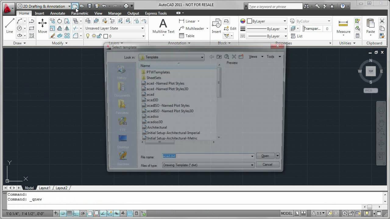
Template Files
AUTOCAD 2026 CURSO - AULA 4 - COMANDO COPY - DESENHANDO

[Curso AutoCAD DO ZERO 2018-2019 -Aula 01] Configure a tela inicial do AutoCAD EM POUCOS MINUTOS

How to Set Up Initial Coordinate Systems and Zones in Civil 3D
5.0 / 5 (0 votes)