PID control of BLDC motor
Summary
TLDRThis presentation covers the PID control of Brushless DC (BLDC) motors, focusing on Model 1, m=6. It explains the working principles of DC and BLDC motors, emphasizing the role of Hall sensors in rotor position control. The mathematical modeling of the motor, including electrical and mechanical components, is discussed in detail. The importance of PID control for optimizing motor performance is highlighted, with a focus on adjusting parameters like proportional, integral, and derivative gains. The goal is to achieve fast response, minimal overshoot, and no steady-state error for efficient motor control.
Takeaways
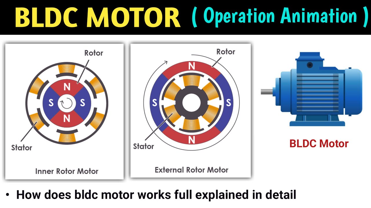
- 😀 BDC (Brushless DC) motors remove physical parts like brushes and commutators, using electronic control to manage the rotor position.
- 😀 The working principle of a DC motor involves supplying voltage to the coil, creating a magnetic field that interacts with a permanent magnet in the stator to cause rotation.
- 😀 The key challenge in BDC motors is the electronic commutation process, which replaces the mechanical commutation of traditional DC motors.
- 😀 The Hall sensor in BDC motors detects the rotor's position by sensing the magnetic field of the rotor's permanent magnet, sending signals to the controller to adjust the motor's motion.
- 😀 The mathematical model of a DC motor involves Kirchhoff’s voltage law (KVL) and Newton's second law, forming equations that describe the electrical and mechanical dynamics of the motor.
- 😀 The transfer function of the BDC motor system is derived to represent the relationship between input voltage and output mechanical position.
- 😀 Key assumptions in modeling BDC motors include neglecting friction constants and certain resistances, focusing on simplifying the transfer function for analysis.
- 😀 PID (Proportional-Integral-Derivative) control is used to optimize motor performance, with KP for rise time, KI for steady-state error, and KD for stability and overshoot reduction.
- 😀 Open-loop analysis is conducted to assess the system’s behavior, using root locus plots to determine the stability and response of the system.
- 😀 PID controller design is iterative, beginning with improving the open-loop response and adjusting PID parameters to achieve the desired transient and steady-state performance.
- 😀 The ultimate goal of PID control in BDC motors is to achieve fast, stable performance with minimal steady-state error and controlled transient response.
Q & A
What is the main advantage of using the EC model in the industry?
-The main advantage of using the EC model in the industry is its ease of control.
What challenge does the commutator pose in DC motor control?
-The commutator in DC motor control poses challenges due to its mechanical wear and tear, which can affect the performance and reliability of the motor.
How does the working principle of a DC motor generate motion?
-The working principle of a DC motor generates motion by supplying voltage to the rotor, which energizes the coils to create a magnetic field that interacts with the permanent magnet in the stator, causing the rotor to spin.
What is the technology used in BLDC motors to improve efficiency?
-BLDC motors use electronic commutation instead of a physical commutator, which reduces wear and tear and increases efficiency.
How does the H sensor work in a BLDC motor?
-The H sensor detects the position of the rotor by sensing the magnetic field from the rotor’s permanent magnet. It then sends this information to the controller, which adjusts the current in the stator coils to control the rotor’s position.
What are the equations used to model the DC motor mathematically?
-The mathematical model of a DC motor includes Kirchhoff’s Voltage Law (KVL) and Newton’s second law. The KVL equation is: V = L(di/dt) + Ri + E, and the mechanical equation is: ΣT = J(dω/dt), where T is the torque and ω is the angular velocity.
What is the significance of the back electromotive force (EMF) in DC motor control?
-The back EMF (E) in DC motor control opposes the applied voltage and is proportional to the speed of the motor. It plays a crucial role in determining the motor’s speed and torque.
How is the transfer function of a BLDC motor obtained?
-The transfer function of a BLDC motor is obtained by substituting the electrical and mechanical equations derived from Kirchhoff’s Voltage Law and Newton’s second law. The final transfer function relates the torque to angular velocity and vice versa.
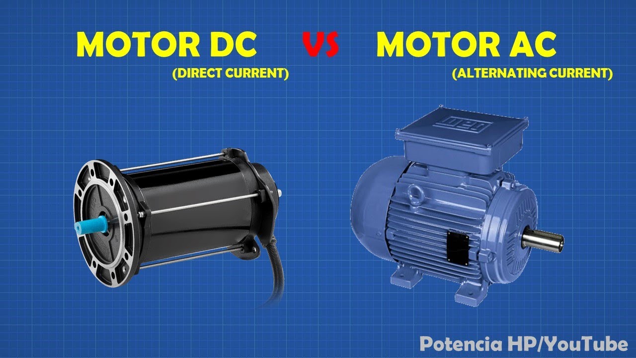
What is the main difference between a normal DC motor and a BLDC motor?
-The main difference is that a BLDC motor does not have brushes and its commutation is electronically controlled, unlike a normal DC motor which uses brushes and a mechanical commutator.
How does the PID controller improve the performance of a motor control system?
-The PID controller improves the performance of a motor control system by adjusting three parameters: the proportional gain (Kp) reduces rise time, the integral gain (Ki) eliminates steady-state error, and the derivative gain (Kd) improves stability and reduces overshoot.
Outlines

This section is available to paid users only. Please upgrade to access this part.
Upgrade NowMindmap

This section is available to paid users only. Please upgrade to access this part.
Upgrade NowKeywords

This section is available to paid users only. Please upgrade to access this part.
Upgrade NowHighlights

This section is available to paid users only. Please upgrade to access this part.
Upgrade NowTranscripts

This section is available to paid users only. Please upgrade to access this part.
Upgrade NowBrowse More Related Video

5.0 / 5 (0 votes)