Membuat Topologi Jaringan 1 Gedung 3 Lantai Menggunakan Cisco Paket Tracer
Summary
TLDRThis video tutorial provides a detailed guide on creating a network topology for a three-floor administration building at Politeknik Negeri Pontianak using Cisco Packet Tracer. It covers the configuration of routers, switches, wireless routers, and PCs across the building’s floors, ensuring seamless communication. The tutorial walks through step-by-step instructions, from wiring and IP addressing to configuring default gateways and testing connectivity between devices. The final setup ensures a fully connected and functional network, providing viewers with a comprehensive understanding of network design and configuration in a multi-floor building.
Takeaways
- 😀 The presentation covers how to design a network topology for a three-story business administration building using Cisco Packet Tracer.
- 😀 The network setup involves a central router, three switches (one for each floor), and wireless routers for communication on each floor.
- 😀 Each floor is equipped with PCs that are connected via switches and routers, with a total of 10 clients across the three floors.
- 😀 Straight cables are used to connect the router to switches, while cross cables connect the switches to wireless routers.
- 😀 The router’s IP configuration includes using IPv4 addresses, such as 128.4.200 for the first router and 192.168.5.200 for the second.
- 😀 A wireless router is used on each floor to distribute the network, although the wireless feature is disabled in the configuration for LAN connectivity.
- 😀 The network configuration involves assigning IP addresses to PCs, ensuring they can communicate with the router’s IP as the default gateway.
- 😀 For each floor, the wireless router is configured with distinct IP addresses to ensure proper network segmentation and communication.
- 😀 After setting up the devices and network, the communication between PCs on the same floor and across floors is tested using ping commands.
- 😀 The final result shows successful network communication between all PCs across the three floors, demonstrating that the network topology is working properly.
Q & A
What is the purpose of the network topology configuration in this tutorial?
-The tutorial demonstrates how to configure a network topology for a three-floor building at a business administration department using Cisco Packet Tracer.
How many floors are involved in this network topology setup?
-The network topology setup involves a building with three floors, each requiring its own network connectivity.
What network devices are used in the topology for this building?
-The setup uses 1 router, 3 switches (one for each floor), 5 wireless routers to distribute the network, and 10 PCs as clients.
What type of cables are used to connect the devices in this network configuration?
-Straight cables are used to connect the router to the switches and the PCs to the router or wireless router. Crossover cables are used to connect switches to wireless routers.
What IP addressing scheme is used for the router and wireless routers?
-The router is assigned static IP addresses like 192.168.4.200 for the first floor and 192.168.5.200 for the second floor. Each wireless router also has a unique IP address to distribute the network.
How are the PCs on each floor configured to communicate with each other?
-Each PC is assigned an IP address within the same network range as their respective wireless router, and the default gateway is set to the router's IP address to allow communication across floors.
What role do the switches play in the network topology?
-The switches are used to connect the router to the wireless routers on each floor and to distribute the network to the PCs, allowing communication within each floor and between floors.
How is communication between PCs on different floors tested?
-Communication is tested by pinging the PCs on different floors. If the ping is successful, it confirms that the network is properly configured and all devices are interconnected.
Why is the wireless router used instead of relying solely on the main router?
-The wireless routers are used to extend the network coverage on each floor and to provide wireless connectivity to the PCs. They help in managing traffic and distributing the network across the three floors.
What happens if the network configuration is done incorrectly, such as using the wrong cables or IP addresses?
-If the configuration is incorrect, the devices may fail to communicate with each other, causing network issues like unreachable PCs, failed pings, or inability to access shared resources across floors.
Outlines

This section is available to paid users only. Please upgrade to access this part.
Upgrade NowMindmap

This section is available to paid users only. Please upgrade to access this part.
Upgrade NowKeywords

This section is available to paid users only. Please upgrade to access this part.
Upgrade NowHighlights

This section is available to paid users only. Please upgrade to access this part.
Upgrade NowTranscripts

This section is available to paid users only. Please upgrade to access this part.
Upgrade NowBrowse More Related Video

Tutorial Topologi Jaringan Sederhana menggunaan Cisco Packet Tracer (Topologi Tree)

Cara Membuat Jaringan Peer To Peer di Cisco Packet Tracer
Getting Started in Cisco Packet Tracer - 2023
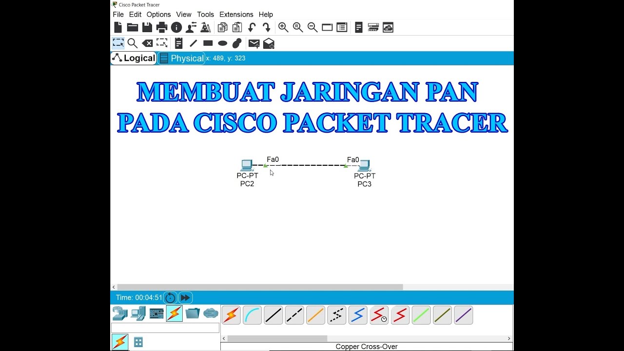
Membuat Jaringan PAN pada Cisco Packet Tracer

Basics of Cisco Packet Tracer (Part 2) | Hub

Jaringan Komputer Sederhana | Tutorial Belajar Online Lengkap CISCO CCNA 200-301 Part 5
5.0 / 5 (0 votes)