Circuit Analysis Using Fourier Series ⭐ RL Circuit Response - Nonsinusoidal Waveform ⭐ Example 1
Summary
TLDRThis video introduces a series on circuit analysis, focusing on the application of Fourier series to analyze non-sinusoidal input signals. The first example explores an RL circuit with a given input voltage expressed as a Fourier series. The video explains how to determine the output signal across the inductor, considering both DC and AC components. It also discusses the circuit's behavior at low and high frequencies and uses the voltage divider rule to find the output voltage. The analysis includes calculating amplitude and phase shifts, transforming the frequency domain solution into the time domain, and plotting the amplitude and phase spectra for a clear understanding of the output signal.
Takeaways
- 🎓 The video series focuses on circuit analysis, specifically discussing the application of Fourier series.
- 🔍 The Fourier series is introduced as a tool for analyzing non-sinusoidal input signals by breaking them into smaller parts.
- 📚 Example 1 involves an RL circuit with a given input voltage represented by a Fourier series expression.
- 🔧 The circuit's response to the input voltage is analyzed, with the output voltage across the inductor being the focus.
- ⚡ The input voltage's Fourier series includes a DC term and frequency-dependent terms (harmonics), with odd values for n.
- 🌉 At very low frequencies, the circuit acts as a short circuit, and at very high frequencies, it acts as an open circuit, making it a high-pass filter.
- 📉 The output voltage is calculated using the voltage divider rule, considering the reactance of the inductor.
- 🔄 The DC component of the output voltage is zero because inductors short out DC.
- 📊 The amplitude and phase of the AC terms are analyzed, with the amplitude decreasing and the phase approaching -90 degrees as frequency increases.
- 📈 The output signal's amplitude and phase spectra are plotted to visualize the signal's behavior across different frequencies.
- 🔗 The video concludes with a summary of the output voltage determination and the plotted spectra, emphasizing the rapid decrease in amplitude for higher harmonics.
Q & A
What is the main topic of the video series?
-The main topic of the video series is circuit analysis, with a focus on discussing the Fourier series in the context of analyzing circuits.
Why is the Fourier series useful in circuit analysis?
-The Fourier series is useful in circuit analysis when dealing with non-sinusoidal input signals, as it allows for breaking down complex signals into smaller, more manageable parts for analysis.
What type of circuit is being analyzed in the first example?
-In the first example, an RL (Resistor-Inductor) circuit is being analyzed, where the input voltage is given by a Fourier series expression.
What are the values of R and L in the given RL circuit?
-The values of R (resistor) and L (inductor) in the given RL circuit are 10 ohms and 4 Henries, respectively.
What is the significance of the DC term in the Fourier series expression of the input voltage?
-The DC term in the Fourier series expression of the input voltage represents the frequency-independent term, which is a constant value separate from the frequency-dependent harmonics.
How does the value of 'k' in the Fourier series expression affect the harmonics?
-The value of 'k' in the Fourier series expression determines the frequency of the harmonics. As 'k' increases, the frequency of the harmonics (n = 2k - 1) also increases, resulting in odd harmonic values such as 1, 3, 5, 7, etc.
What is the fundamental frequency (ω0) in the context of this video?
-The fundamental frequency (ω0) in this context is given by π radians per second, which is the frequency of the first harmonic in the Fourier series.
Why does the output voltage across the inductor approach zero for very low frequencies?
-For very low frequencies, the inductor behaves like a short circuit, which means the output voltage across it approaches zero because the current flows through the path of least impedance, bypassing the inductor.
How is the output voltage of the circuit calculated?
-The output voltage of the circuit is calculated using the voltage divider rule, which states that the output voltage is the input voltage multiplied by the ratio of the reactance of the inductor to the total impedance of the circuit.
What is the significance of the amplitude and phase of the input voltage in the analysis?
-The amplitude and phase of the input voltage are significant because they determine the magnitude and timing of the voltage waveform. In the analysis, these properties are used to calculate the response of the circuit to each harmonic component of the input signal.
How does the video script describe the transition from frequency domain to time domain for the output voltage?
-The script describes the transition from frequency domain to time domain by expressing the output voltage as a sum of cosine terms, each with its amplitude and phase shift, which are derived from the analysis in the frequency domain.
What is the purpose of plotting the amplitude and phase spectrum of the output voltage?
-Plotting the amplitude and phase spectrum of the output voltage helps visualize the contribution of each harmonic to the total output signal and understand how the circuit responds to different frequencies.
Why are even terms not present in the output for this specific RL circuit?
-Even terms are not present in the output for this specific RL circuit because the input signal, as represented by its Fourier series, only contains odd harmonics, and the circuit's response does not generate even harmonics.
Outlines

This section is available to paid users only. Please upgrade to access this part.
Upgrade NowMindmap

This section is available to paid users only. Please upgrade to access this part.
Upgrade NowKeywords

This section is available to paid users only. Please upgrade to access this part.
Upgrade NowHighlights

This section is available to paid users only. Please upgrade to access this part.
Upgrade NowTranscripts

This section is available to paid users only. Please upgrade to access this part.
Upgrade NowBrowse More Related Video
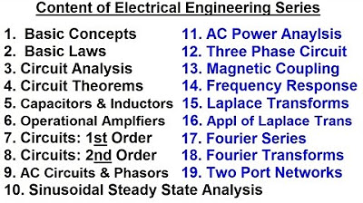
Electrical Engineering: Basic Concepts (1 of 7) Content
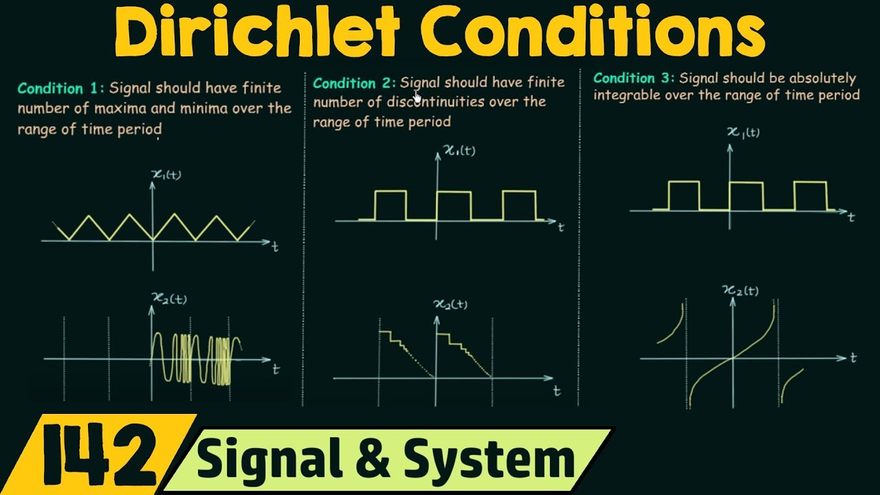
Conditions for Existence of Fourier Series (Dirichlet Conditions)
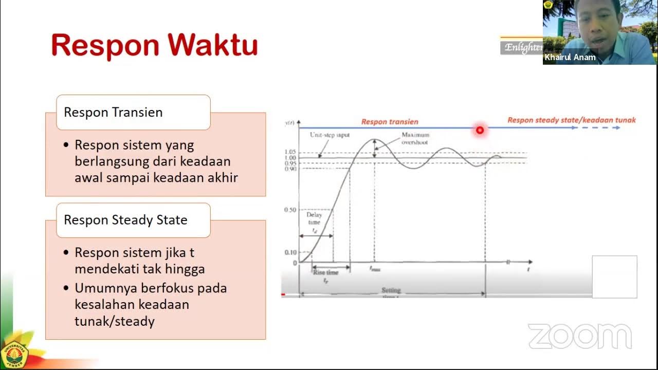
Sistem Kontrol #3a: Analisis Repon Sistem - Pendahuluan
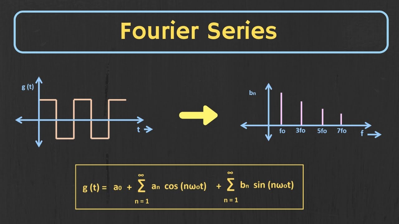
Introduction to Fourier Series | Trigonometric Fourier Series Explained

Introduction to Signals and Systems
Exponential Fourier Series Explained | Concept of Negative Frequency Explained
5.0 / 5 (0 votes)