Capacitive Complex Impedance (Full Lecture)
Summary
TLDRIn this lecture from Big Bad Tech, the focus is on capacitive complex impedance in AC circuits. It covers the basics of how capacitors, represented as complex impedances, react to alternating current, with the key takeaway being the inverse relationship between impedance magnitude and frequency. Capacitors display a constant phase shift of 90°, with their impedance decreasing at higher frequencies and increasing at lower frequencies. The lecture provides practical examples, such as calculating the impedance of a 22 µF capacitor at different frequencies and solving for other circuit parameters like frequency and capacitance. This fundamental concept prepares viewers for further exploration in AC circuit analysis.
Takeaways
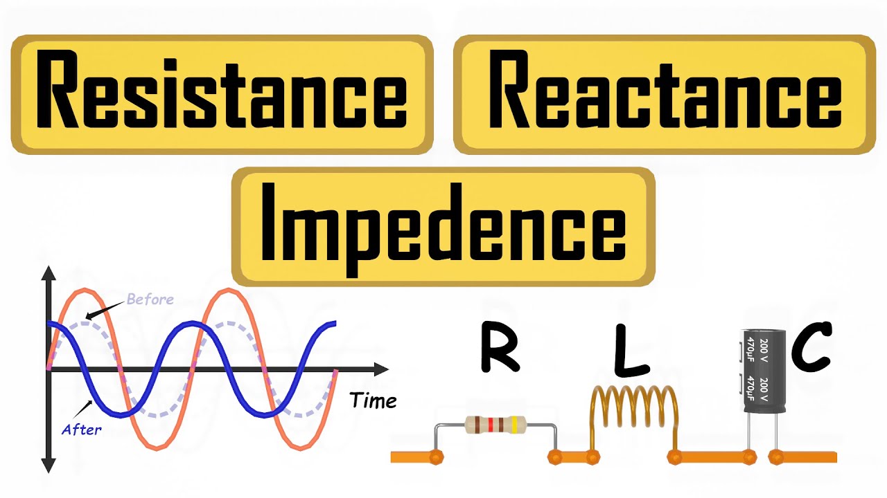
- 😀 Resistors, capacitors, and inductors are fundamental components in AC circuits, with capacitors and inductors being reactive elements that store and return energy.
- 😀 Capacitors lead current and voltage is shifted behind them, while inductors lag current and voltage leads them, a key distinction in reactive elements.
- 😀 Complex impedance is a way to represent the effect of reactive elements (capacitors and inductors) on AC circuits using complex numbers.
- 😀 Resistors in AC circuits have impedance that is purely real (resistive) and independent of frequency, and are represented in the positive real horizontal axis of the impedance plane.
- 😀 Capacitors in AC circuits have impedance that is purely imaginary (reactive), with the magnitude inversely proportional to frequency, and are represented in the negative imaginary axis.
- 😀 Inductors in AC circuits also have impedance that is purely imaginary, with the magnitude directly proportional to frequency, and are represented in the positive imaginary axis.
- 😀 The impedance of a capacitor is calculated using the formula Zc = 1/(2πfC), where f is frequency and C is capacitance. The angle for capacitors is always 90°.
- 😀 The impedance of an inductor is calculated using the formula Zl = 2πfL, where f is frequency and L is inductance. The angle for inductors is always +90°.
- 😀 The magnitude of capacitive complex impedance decreases as frequency increases, and increases as frequency decreases, which follows an inversely proportional relationship.
- 😀 A practical example: Doubling the frequency of a 22 microfarad capacitor reduces its impedance by half, while halving the frequency doubles its impedance, with the angle remaining fixed at 90°.
Q & A
What is the main objective of this lecture on capacitive complex impedance?
-The main objective is to learn how to represent capacitors as complex impedances for the purposes of AC circuit analysis.
What are the two tools used for AC circuit analysis of reactive elements like capacitors and inductors?
-The two tools used are time-consuming calculus-based techniques and simpler algebraic techniques involving complex numbers.
What does the term 'impedance' represent in AC circuit analysis?
-Impedance is a generalization of resistance for AC circuits and includes both resistance and reactive elements like capacitance and inductance, accounting for phase shifts.
How are resistors represented as complex impedances?
-Resistors are represented as complex impedances that exist solely along the real horizontal x-axis in the impedance domain, with a magnitude equal to the resistance value and an angle of zero.
What is the formula for calculating capacitive complex impedance?
-The formula for calculating capacitive complex impedance is Zc = 1 / (2π * frequency * capacitance), with an angle of -90° in polar format.
How does frequency affect the magnitude of capacitive impedance?
-The magnitude of capacitive impedance is inversely proportional to frequency. As frequency increases, the impedance decreases, and as frequency decreases, the impedance increases.
What happens to the capacitive complex impedance if the frequency is doubled?
-If the frequency is doubled, the magnitude of the capacitive complex impedance will decrease by half, but the angle remains fixed at -90°.
How would you express the complex impedance of a 22 microfarad capacitor at 60 Hz in polar format?
-The complex impedance would be expressed as approximately 12.6 ohms at an angle of -90°.
What is the significance of the -90° angle in capacitive complex impedance?
-The -90° angle indicates that the current through a capacitor always leads the voltage by 90°, reflecting the time-shifted nature of the response.
What is the relationship between the magnitude of capacitive impedance and frequency?
-The magnitude of capacitive impedance decreases as frequency increases and increases as frequency decreases, which is consistent with the behavior of capacitors in AC circuits.
Outlines

This section is available to paid users only. Please upgrade to access this part.
Upgrade NowMindmap

This section is available to paid users only. Please upgrade to access this part.
Upgrade NowKeywords

This section is available to paid users only. Please upgrade to access this part.
Upgrade NowHighlights

This section is available to paid users only. Please upgrade to access this part.
Upgrade NowTranscripts

This section is available to paid users only. Please upgrade to access this part.
Upgrade NowBrowse More Related Video

Rangkaian RLC Seri

What the Heck is Reactance and Why is it So Weird?!?

AC Through Series RC Circuit - AC Circuits - Basic Electrical Engineering

Rangkaian Resistif, Induktif, dan Kapasitif | Rangkaian AC | Part 1 | Fisika Dasar
What are Resistance Reactance Impedance

Praktikum Fisika Dasar || ARUS BOLAK BALIK
5.0 / 5 (0 votes)