AC Through Series RC Circuit - AC Circuits - Basic Electrical Engineering
Summary
TLDRThis video explains the behavior of alternating current (AC) in a circuit composed of a resistor and a capacitor in series. It covers the relationships between voltage, current, and impedance, illustrating how current leads voltage in a capacitive circuit by an angle phi. The video also introduces key concepts such as real power, apparent power, and reactive power, highlighting their mathematical relationships and units. The power factor is discussed, noting its leading nature in capacitive circuits. Through phasor diagrams and equations, the video provides a comprehensive understanding of AC circuit dynamics.
Please replace the link and try again.
Q & A
What is the main topic of the video?
-The video discusses the behavior of alternating current (AC) when passed through a series connection of resistance and capacitance.
How is the voltage drop across the resistor calculated?
-The voltage drop across the resistor (V_R) is calculated using Ohm's law: V_R = I * R, where I is the current flowing through the resistor and R is the resistance.
What is the capacitive reactance (X_C), and how is it defined?
-The capacitive reactance (X_C) is defined as the opposition to the flow of AC current in a capacitor, given by the formula X_C = 1 / (2πfC), where f is the frequency and C is the capacitance.
What phase relationship exists between voltage and current in a capacitive circuit?
-In a capacitive circuit, the current leads the voltage by 90 degrees, or equivalently, the voltage lags the current by 90 degrees.
What is the impedance (Z) of the circuit, and how is it calculated?
-The impedance (Z) is the total opposition to the flow of AC current, calculated using the formula Z = √(R² + X_C²), where R is the resistance and X_C is the capacitive reactance.
What does the power triangle represent in an RC circuit?
-The power triangle represents the relationship between real power (P), reactive power (Q), and apparent power (S) in an RC circuit, with P on the x-axis, Q on the imaginary axis, and S as the diagonal.
What is the formula for average power (P_avg) in the circuit?
-The average power (P_avg) in the circuit is given by P_avg = V_RMS * I_RMS * cos(ϕ), where V_RMS and I_RMS are the root mean square values of voltage and current, and ϕ is the phase angle.
What is the significance of the power factor in AC circuits?
-The power factor indicates the efficiency of power usage in an AC circuit and is defined as cos(ϕ), where ϕ is the phase angle between voltage and current. It determines how much of the total power is used effectively.
How does the nature of the power factor differ between inductive and capacitive circuits?
-In inductive circuits, the power factor is lagging because the current lags the voltage. In capacitive circuits, the power factor is leading because the current leads the voltage.
What are the units for real power (P), reactive power (Q), and apparent power (S)?
-The unit for real power (P) is watts (W) or kilowatts (kW), for reactive power (Q) it is volt-amperes reactive (VAR) or kilovolt-amperes reactive (kVAR), and for apparent power (S) it is volt-amperes (VA) or kilovolt-amperes (kVA).
Outlines

This section is available to paid users only. Please upgrade to access this part.
Upgrade NowMindmap

This section is available to paid users only. Please upgrade to access this part.
Upgrade NowKeywords

This section is available to paid users only. Please upgrade to access this part.
Upgrade NowHighlights

This section is available to paid users only. Please upgrade to access this part.
Upgrade NowTranscripts

This section is available to paid users only. Please upgrade to access this part.
Upgrade NowBrowse More Related Video
AC Through Series RL Circuit - AC Circuits - Basic Electrical Engineering
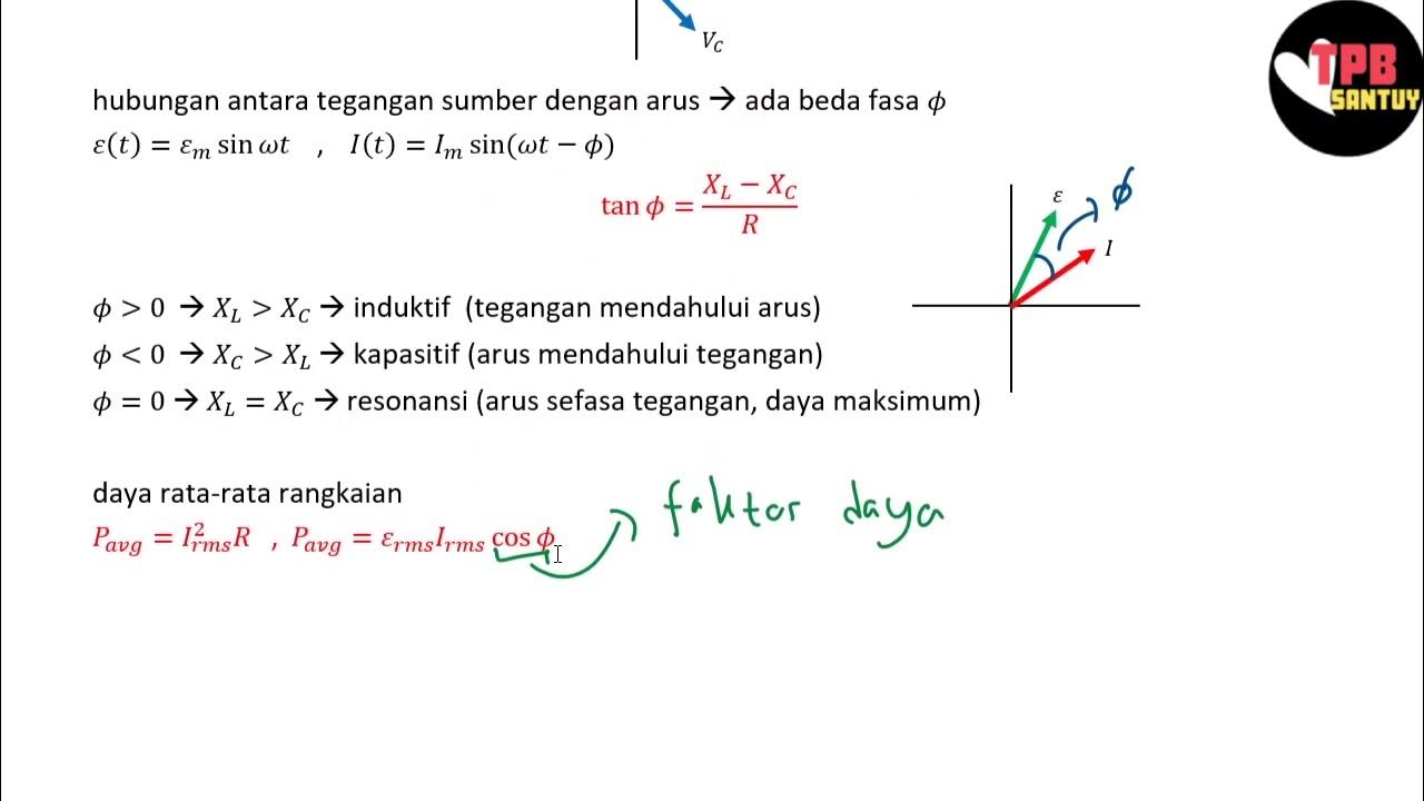
Rangkaian Seri RLC | Rangkaian AC | Part 2 | Fisika Dasar
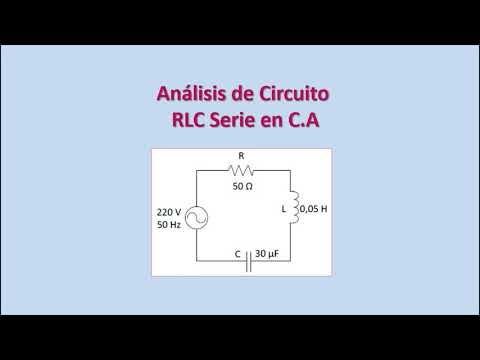
Análisis de Circuitos RLC en Corriente Alterna. Diagrama Fasorial. Ejercicio Resuelto.
Three Phase AC Circuits : Problem 1 - Three Phase Circuits - Basic Electrical Engineering

Rangkaian RC (Resistor-Kapasitor) | Rangkaian DC | Part 5 | Fisika Dasar

MODUL1 PENYEARAH 1PHASE (HALF WAVE DAN FULL WAVE) MENGGUNAKAN SIMULINK MATLAB
5.0 / 5 (0 votes)