Rangkaian Resistif, Induktif, dan Kapasitif | Rangkaian AC | Part 1 | Fisika Dasar
Summary
TLDRThis video tutorial delves into the basics of Alternating Current (AC) circuits, covering key components like resistive, inductive, and capacitive circuits. It explains how AC voltage and current fluctuate over time, with a focus on the concept of RMS (Root Mean Square) values. The video demonstrates how voltage and current behave differently in resistive, inductive, and capacitive circuits, detailing their phase relationships using phasor diagrams. The content aims to help viewers grasp fundamental AC circuit principles, such as Ohm's Law and the effects of different components on the overall circuit behavior.
Takeaways
- 😀 AC circuits alternate direction periodically, with voltage and current reversing directions, as opposed to DC circuits where the direction remains constant.
- 😀 The RMS (Root Mean Square) value of AC voltage and current is crucial as it represents the effective value, which can be measured using a voltmeter.
- 😀 In an AC circuit, the voltage and current waveforms are sinusoidal, and their relationship can be described using mathematical functions like sine or cosine.
- 😀 The relationship between voltage and current in a resistive AC circuit follows Ohm's Law, where voltage equals the current multiplied by resistance.
- 😀 In a purely resistive AC circuit, voltage and current are in phase, meaning they reach their maximum and minimum values simultaneously.
- 😀 Phase diagrams or phasors are used to represent the relationships between voltage and current in AC circuits, treating them as vectors in a graphical format.
- 😀 In an inductive AC circuit, the voltage leads the current by 90 degrees, meaning the voltage reaches its peak before the current does.
- 😀 The reactance in an inductive circuit (XL) is proportional to the frequency of the AC supply and the inductance of the inductor.
- 😀 In a capacitive AC circuit, the current leads the voltage by 90 degrees, meaning the current reaches its peak before the voltage.
- 😀 The reactance in a capacitive circuit (XC) depends on the frequency of the AC supply and the capacitance of the capacitor.
- 😀 Understanding the behavior of resistive, inductive, and capacitive components in AC circuits is essential for analyzing their effects on voltage, current, and phase relationships.
Q & A
What is an AC circuit, and how does it differ from a DC circuit?
-An AC circuit, or alternating current circuit, involves a current that changes direction periodically, unlike a DC (direct current) circuit, where the current flows in only one direction. AC circuits are used in most power distribution systems, like those of the electricity grid.
What is the significance of RMS (Root Mean Square) value in AC circuits?
-The RMS value is the effective value of an alternating current or voltage. It represents the equivalent steady DC value that would produce the same power dissipation in a resistive load. It is important because instruments like voltmeters measure this value in AC circuits.
What are the main types of components used in AC circuits?
-The main components in AC circuits are resistive, inductive, and capacitive elements. Each of these components has different properties affecting the voltage and current behavior in the circuit.
What is a resistive AC circuit, and how does it behave?
-A resistive AC circuit contains only a resistor. In such a circuit, the current and voltage waveforms are in phase, meaning they reach their maximum and minimum values at the same time. There is no phase shift between the voltage and current.
How is Ohm’s Law applied in resistive AC circuits?
-In resistive AC circuits, Ohm's Law applies similarly to DC circuits. The voltage across the resistor equals the current multiplied by the resistance (V = I * R), and the current is directly proportional to the voltage.
What is an inductive AC circuit, and how does it behave?
-An inductive AC circuit contains an inductor, which creates a phase difference between the voltage and the current. In such a circuit, the voltage leads the current by 90 degrees. This means that the voltage reaches its peak before the current does.
What is reactance in an inductive circuit?
-Reactance is the opposition that an inductor provides to the alternating current. It is represented by the symbol XL and is calculated as XL = ωL, where ω is the angular frequency, and L is the inductance of the coil.
How does the current behave in an inductive AC circuit?
-In an inductive AC circuit, the current lags behind the voltage. The phase difference between the current and voltage is 90 degrees, meaning the current reaches its peak value after the voltage.
What is a capacitive AC circuit, and how does it behave?
-A capacitive AC circuit contains a capacitor. In such a circuit, the current leads the voltage by 90 degrees. This means the current reaches its peak before the voltage does, which is the opposite behavior compared to an inductive circuit.
What is the reactance in a capacitive AC circuit?
-The reactance in a capacitive AC circuit is called capacitive reactance, denoted by XC. It is calculated as XC = 1 / (ωC), where ω is the angular frequency, and C is the capacitance of the capacitor.
Outlines

This section is available to paid users only. Please upgrade to access this part.
Upgrade NowMindmap

This section is available to paid users only. Please upgrade to access this part.
Upgrade NowKeywords

This section is available to paid users only. Please upgrade to access this part.
Upgrade NowHighlights

This section is available to paid users only. Please upgrade to access this part.
Upgrade NowTranscripts

This section is available to paid users only. Please upgrade to access this part.
Upgrade NowBrowse More Related Video
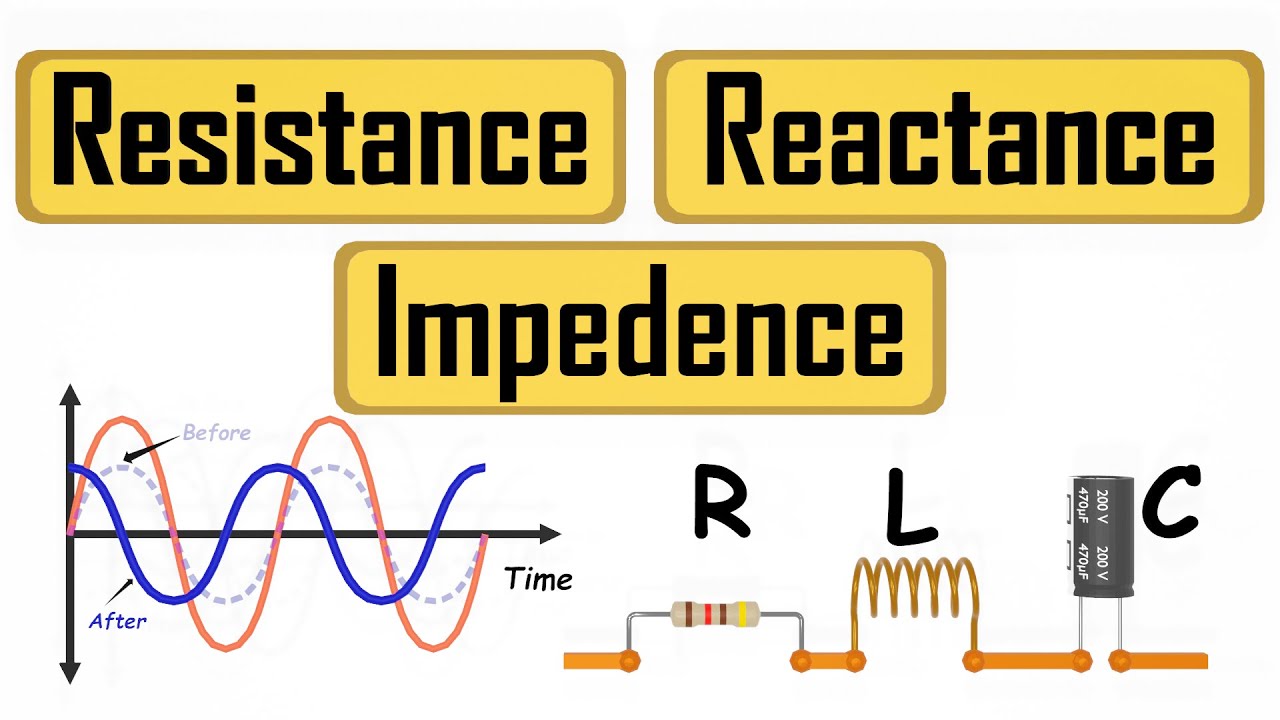
What are Resistance Reactance Impedance

Simulasi Arus dan Tegangan Bolak-Balik dengan Phet

FISIKA Kelas 12 - Listrik Bolak Balik (AC) | GIA Academy

Basic Electrical Engineering | Module 2 | Analysis of Single Phase AC | Part 1 (Lecture 12)
A.C. CIRCUIT | A.C. FUNDAMENTALS | COMPLETE STUDY OF PURE A.C. CIRCUITS | LECTURE 3 IN HINDI
AC Through Series RLC Circuit - AC Circuits - Basic Electrical Engineering
5.0 / 5 (0 votes)