Analisis Rangkaian AC | Rangkaian AC | Part 3 | Fisika Dasar
Summary
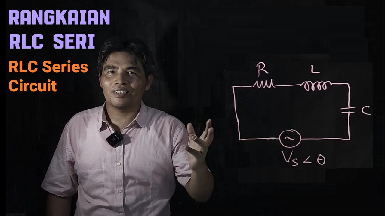
TLDRThis video lesson focuses on analyzing AC circuits, covering key concepts such as impedance, phase differences, resonance, and power calculations. It explains the relationships between voltage, current, and components like resistors, inductors, and capacitors in AC circuits. The lesson walks through practical examples and calculations, including how to find current as a function of time, impedance, and power. Additionally, it discusses resonance conditions, using inductance and capacitance to achieve resonance, and provides techniques for determining voltage across components like capacitors and inductors. The video aims to simplify complex AC circuit analysis for better understanding.
Takeaways
- 😀 The lesson covers AC circuit analysis, focusing on problems involving resistors, inductors, and capacitors.
- 😀 The script discusses important formulas related to inductive reactance (XL), capacitive reactance (XC), impedance, and phase differences.
- 😀 It highlights the necessity of understanding the relationships between voltage, current, and components in an AC circuit.
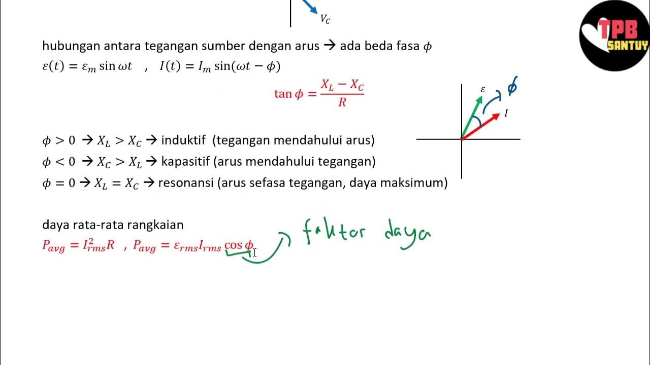
- 😀 The key concept of phase difference is introduced, with voltage and current potentially having a phase shift, which must be considered in calculations.
- 😀 The first problem involves a circuit with only a resistor and inductor, where the voltage source is given as 30 Sin(100t + 12°).
- 😀 To calculate the current as a function of time, the formula for maximum current, impedance, and phase difference is used.
- 😀 The impedance in the first circuit is derived from the formula Z = √(R² + XL²), where XL = ωL (inductive reactance).
- 😀 The phase difference is calculated using the relationship between inductive reactance and resistance, resulting in a phase shift of 1.9°.
- 😀 Power calculations are performed using RMS (Root Mean Square) values, and the average power is found to be 1.5 W for the first problem.
- 😀 The second part of the problem involves an RLC circuit with a resonant frequency, where the condition for resonance is XL = XC, leading to the calculation of inductance (L).
- 😀 When inductance is provided, the voltage across the capacitor and other components is analyzed using phase diagrams, and specific formulas are used to determine voltages and phase shifts for each component.
Q & A
What is the main focus of this video?
-The video focuses on the analysis of AC circuits, including concepts such as impedance, phase differences, current and voltage calculations, and resonance in RLC circuits.
How do you calculate the current as a function of time in an AC circuit?
-The current as a function of time can be calculated using the formula I(t) = I_max * sin(ωt + φ), where I_max is the maximum current, ω is the angular frequency, t is time, and φ is the phase difference.
What role does impedance play in an AC circuit?
-Impedance (Z) determines the opposition to current flow in an AC circuit. It is influenced by the values of resistance (R), inductive reactance (XL), and capacitive reactance (XC), and is critical for calculating the current in the circuit.
What is the phase difference in an AC circuit and how is it determined?
-The phase difference is the difference in phase between the voltage and current. It can be determined by calculating the reactance of the inductor (XL) and capacitor (XC) and using the formula tan(φ) = (XL - XC) / R, where φ is the phase difference.
What is resonance in an RLC circuit and how do you achieve it?
-Resonance in an RLC circuit occurs when the inductive reactance (XL) equals the capacitive reactance (XC). This can be achieved by selecting the right values for the inductor (L) and capacitor (C), ensuring that the circuit operates at the resonance frequency, where XL = XC.
How do you calculate the inductance (L) for resonance in an RLC circuit?
-The inductance for resonance can be calculated using the formula L = 1 / (ω^2 * C), where ω is the angular frequency and C is the capacitance. This ensures that XL = XC at resonance.
What is the relationship between current and voltage in an AC circuit?
-In an AC circuit, the current and voltage are related by impedance. The phase difference between them indicates whether the current leads or lags the voltage, and this relationship is affected by the components in the circuit, such as resistors, inductors, and capacitors.
How do you calculate the average power in an AC circuit?
-The average power in an AC circuit can be calculated using the formula P_avg = I_RMS^2 * R, where I_RMS is the root mean square of the current and R is the resistance. The relationship between I_max and I_RMS is I_RMS = I_max / √2.
How do you calculate the voltage across a capacitor in an AC circuit?
-To calculate the voltage across a capacitor, use the formula V_C = I_max * XC, where I_max is the maximum current and XC is the capacitive reactance. The phase difference between the current and voltage across the capacitor is 90°, meaning the voltage lags the current by 90°.
What is the voltage across a resistor and inductor in an AC circuit and how is it calculated?
-The voltage across a resistor and inductor in an AC circuit can be calculated by determining the resultant voltage of the two components. Since they are 90° out of phase, the voltages are added as vectors: V_RL_max = √(V_R_max^2 + V_L_max^2).
Outlines

This section is available to paid users only. Please upgrade to access this part.
Upgrade NowMindmap

This section is available to paid users only. Please upgrade to access this part.
Upgrade NowKeywords

This section is available to paid users only. Please upgrade to access this part.
Upgrade NowHighlights

This section is available to paid users only. Please upgrade to access this part.
Upgrade NowTranscripts

This section is available to paid users only. Please upgrade to access this part.
Upgrade NowBrowse More Related Video
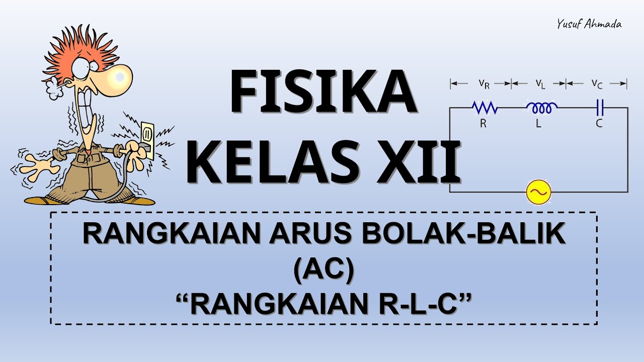
FISIKA KELAS XII | RANGKAIAN ARUS BOLAK-BALIK (AC) - PART 2 : RANGKAIAN RLC
Rangkaian Seri RLC | Rangkaian AC | Part 2 | Fisika Dasar
Praktikum Fisika Dasar || ARUS BOLAK BALIK
AC Through Series RL Circuit - AC Circuits - Basic Electrical Engineering
Rangkaian RLC Seri

What the Heck is Reactance and Why is it So Weird?!?
5.0 / 5 (0 votes)