How to Create a Simple LAN Network - Cisco Packet Tracer
Summary
TLDRIn this video tutorial, the creator demonstrates how to set up a simple Local Area Network (LAN) using Cisco Packet Tracer. Viewers are guided step-by-step through the process of adding devices such as a switch and multiple PCs, wiring them together with straight-through cables, and assigning IP addresses. The video also covers testing the configuration by pinging between the PCs to ensure connectivity. Additionally, the creator explains how to add a third PC and test communication between all devices. The video concludes with a reminder to like, comment, share, and subscribe for more tutorials.
Takeaways
- 😀 The video demonstrates how to create a simple LAN network using Cisco Packet Tracer software.
- 😀 Viewers can download Cisco Packet Tracer from a link provided in the description if they don’t have it installed.
- 😀 Cisco Packet Tracer's interface has changed, now featuring a blue and black design, replacing the older yellow screen.
- 😀 To create a basic network, you'll need a switch and two PCs, which can be dragged and dropped into the workspace.
- 😀 To delete components, click the 'cross' icon, select the item, and click again to remove it.
- 😀 For configuring the network, users need to connect the PCs to the switch using 'straight cables'.
- 😀 IP configuration for the switch and PCs is done by assigning appropriate IP addresses (e.g., 192.168.30.1 for the switch).
- 😀 You can copy and paste IP addresses from one configuration to another to speed up the process.
- 😀 Once all devices are configured, users can test connectivity between the PCs using the 'ping' command.
- 😀 If the 'ping' is successful (reply from the IP address), the configuration is correct. If it fails, there may be an issue with the setup.
Q & A
What software is being used to create the simple LAN network?
-The software being used is Cisco Packet Tracer, a network simulation tool.
What type of switch is recommended for this tutorial?
-The recommended switch is the Cisco 2950-24, which has 24 ports.
How many PCs are initially configured in the tutorial?
-Two PCs are initially configured in the tutorial, but the speaker mentions adding more later if needed.
How are the devices connected in the network?
-The devices are connected using Straight-Through cables. PC0 is connected to FastEthernet0/1 on the switch, and PC1 is connected to FastEthernet0/2.
What IP address is assigned to the switch in the network?
-The switch is assigned the IP address 192.168.30.1.
How are the IP addresses configured on the PCs?
-PC0 is assigned the IP address 192.168.30.2, and PC1 is assigned the IP address 192.168.30.3. Both PCs use the switch's IP address (192.168.30.1) as the default gateway.
What command is used to test the network connection between the PCs?
-The 'ping' command is used to test the network connection between the PCs. For example, pinging from PC0 to PC1 with the command 'ping 192.168.30.3'.
What should happen if the network configuration is correct during the ping test?
-If the configuration is correct, a successful reply will be received, indicating that the network connection between the PCs is working.
How is the default gateway configured on the PCs?
-The default gateway is configured by assigning the IP address of the switch (192.168.30.1) as the default gateway for both PCs.
What should you do if you want to add a third PC to the network?
-To add a third PC, you can drag and drop a new PC from the device list, connect it to the switch using a Straight-Through cable, and assign it a unique IP address, such as 192.168.30.4, along with the same default gateway (192.168.30.1).
Outlines

This section is available to paid users only. Please upgrade to access this part.
Upgrade NowMindmap

This section is available to paid users only. Please upgrade to access this part.
Upgrade NowKeywords

This section is available to paid users only. Please upgrade to access this part.
Upgrade NowHighlights

This section is available to paid users only. Please upgrade to access this part.
Upgrade NowTranscripts

This section is available to paid users only. Please upgrade to access this part.
Upgrade NowBrowse More Related Video
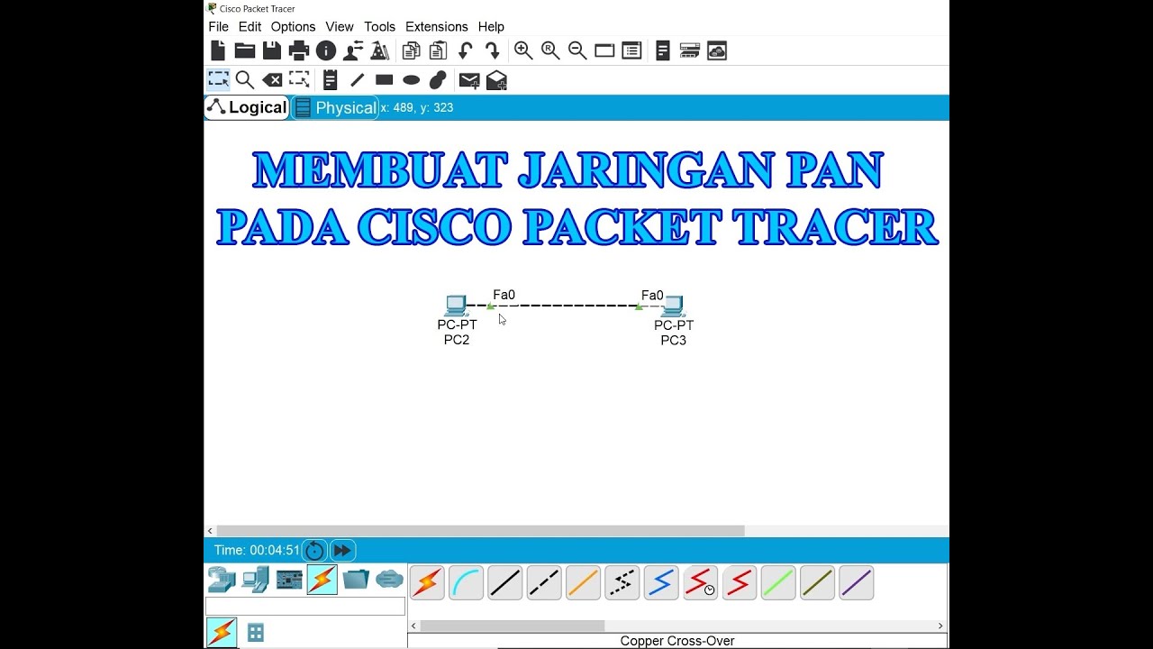
Membuat Jaringan PAN pada Cisco Packet Tracer
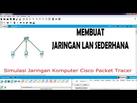
Cara Membuat Jaringan LAN Sederhana Cisco Packet Tracer
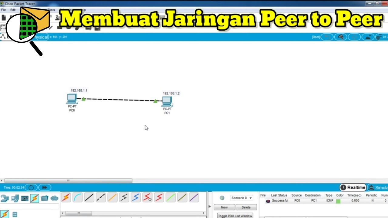
Cara Membuat Jaringan Peer To Peer di Cisco Packet Tracer

Basics of Cisco Packet Tracer (Part 2) | Hub

Netzwerktutorial: Cisco Packet Tracer - Installation, Konfiguration & ein erster Aufbau
Konfigurasi Access Point Cisco di Packet Tracer
5.0 / 5 (0 votes)