P & ID Diagram. How To Read P&ID Drawing Easily. Piping & Instrumentation Diagram Explained.
Summary
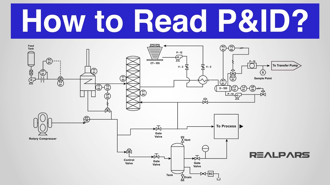
TLDRIn this video from Instrumentation Academy, viewers are introduced to P&ID (Piping and Instrumentation Diagram), a crucial diagram used to represent piping, process equipment, instrumentation, and control devices in a plant. The video explains the various symbols and lines used in P&IDs, such as those for valves, instruments, and piping connections, as well as revision methods and hazard ratings. It also covers important concepts like instrument tag numbers, control valves, and line numbering, providing a comprehensive overview for anyone interested in understanding process diagrams and plant systems.
Takeaways
- 😀 P&ID (Piping and Instrumentation Diagram) is a detailed diagram showing piping, process equipment, instrumentation, and control devices.
- 😀 P&IDs are essential for identifying components, understanding instrument connections, and displaying process functions in a plant.
- 😀 Thick continuous lines represent pipes, and lines crossing without a break indicate connected pipes, while a break shows they are not connected.
- 😀 Flow direction in a P&ID is shown with solid arrowheads on the lines representing pipes.
- 😀 Revisions in P&IDs are indicated with cloud symbols or triangles with revision numbers.
- 😀 Each P&ID drawing includes a process flow tag to show where a pipe is coming from and where it's going.
- 😀 Hazard levels are shown on P&IDs to indicate the risk level of the product in the pipe, such as medium, low, or negligible hazard.
- 😀 Instrument symbols on P&IDs indicate the device type, location, and its function based on shapes and text within the symbols.
- 😀 Instrument Tag Numbers contain an alphanumeric code to describe the instrument's functionality and its unique loop number in the system.
- 😀 Control valves in P&IDs are represented with specific symbols that may include actuators for remote operation.
- 😀 Line symbols in P&IDs differentiate between various mediums, such as solid lines for main piping, thin lines for instrumentation, and dashed lines for electrical signals.
Q & A
What is a P&ID and what does it represent?
-A P&ID (Piping and Instrumentation Diagram) is a detailed diagram that represents the piping, process equipment, instrumentation, and control devices in a process plant. It shows how instruments are connected and the layout of the plant components.
What is the significance of the symbols used in a P&ID?
-The symbols used in a P&ID are standardized and based on the International Society of Automation. They provide a visual representation of various components like pipes, instruments, valves, and controllers, helping to understand their functionality and locations within the plant.
How are revisions indicated in a P&ID drawing?
-Revisions in a P&ID drawing are indicated using two methods: the cloud method (where changes are enclosed in a hand-drawn cloud shape) and the triangle method (where a triangle with the revision number is placed next to the revised area).
What does the direction of flow in a P&ID represent?
-The direction of flow in a P&ID is represented by solid arrows on the piping lines. It shows the movement of fluids within the piping system, helping to visualize the process.
What is the purpose of the Process Flow Tag in P&IDs?
-The Process Flow Tag is used to indicate the source and destination of pipelines in the plant, referencing the previous and next P&ID drawing numbers. This helps in understanding the path of the fluid or material being transported.
What do the various line types in a P&ID represent?
-Different line types in a P&ID represent different mediums or signals: solid lines for main piping, thin lines for impulse or instrument piping, dashed lines for electrical signals, and slanted lines for pneumatic signals.
What does an instrument tag number signify in a P&ID?
-An instrument tag number is an alphanumeric code that uniquely identifies an instrument and its function. It has two parts: the upper line indicates the instrument's functionality, and the lower line represents the loop number corresponding to the equipment in the plant.
What are the different types of instruments represented in a P&ID?
-Instruments in a P&ID can be field-mounted (represented by a circle with no line), control panel-mounted (circle with a single horizontal line), or mounted in remote locations (circle with double horizontal lines). These symbols show where the instruments are located and how they are controlled.
How are control valves represented in a P&ID?
-Control valves in a P&ID are represented by combining valve symbols with actuator symbols. If no actuator is shown, it can be assumed that the valve is manually operated with a hand wheel.
What does a valve actuator do in a P&ID?
-A valve actuator is a device used to operate a valve remotely or automatically. It is typically used to increase the mechanical advantage, allowing precise control of valve operation, and is often combined with the valve symbol in a P&ID to show its function.
Outlines

This section is available to paid users only. Please upgrade to access this part.
Upgrade NowMindmap

This section is available to paid users only. Please upgrade to access this part.
Upgrade NowKeywords

This section is available to paid users only. Please upgrade to access this part.
Upgrade NowHighlights

This section is available to paid users only. Please upgrade to access this part.
Upgrade NowTranscripts

This section is available to paid users only. Please upgrade to access this part.
Upgrade NowBrowse More Related Video

P&ID CHECKING (COMMISSIONING)
How to Read a P&ID? (Piping & Instrumentation Diagram)
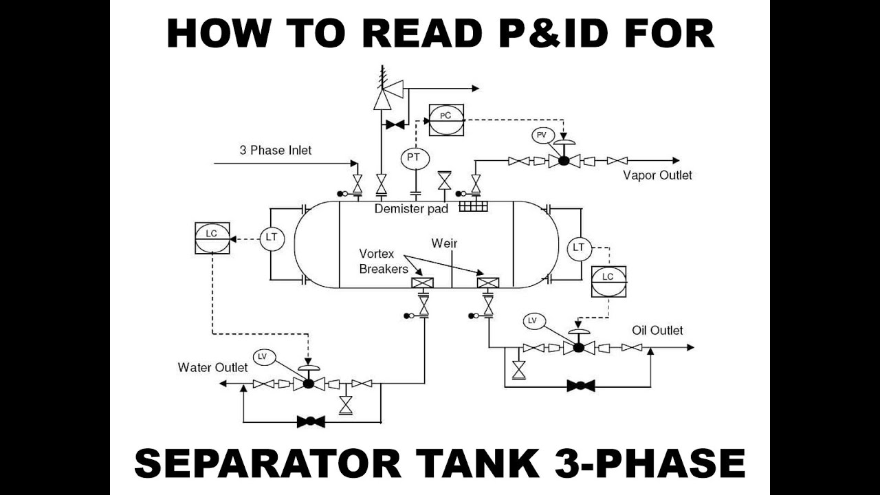
How To Read P&ID Diagram for Separator Tank (3-Phase) in Malay - Nazmi Ismail

Top 30 Instrumentation and control Interviews Questions & Answers

Key P&ID Details for HAZOPS - A HAZOP Crash Course

What Is Industrial Instrumentation? Start Here! 💡 Ep1
5.0 / 5 (0 votes)