PART 1 - MERAKIT SMART DOOR LOCK - MC KIT RFID - DEVKIT VI VERSION, KOMPONEN
Summary
TLDRIn this tutorial, the presenter demonstrates how to create an IoT-based smart door lock system using an ESP32 development board and RFID components. The video covers the necessary hardware, including the ESP32 board, LCD, RFID reader, solenoid lock, and various other components such as resistors, transistors, and sensors. The tutorial guides viewers through the assembly process, explaining the function of each component and how they work together to control the door lock system using RFID cards or key fobs. The session concludes by preparing the system for programming and testing.
Takeaways
- 😀 The tutorial demonstrates how to build an IoT system using the ESP32 DevKit V1 and an RFID-based smart lock system.
- 😀 The ESP32 DevKit V1 is used for IoT applications and features a USB Type-C connector for easy computer connectivity.
- 😀 The LCD 16x2 screen, equipped with I2C communication, will be used for display purposes in the system.
- 😀 The project involves using a buzzer to produce sound when a card is detected by the RFID system.
- 😀 The TIP41C transistor is used in the project as a switch to control high currents and voltages.
- 😀 The MP1584 step-down module provides a 5V output from a 7V-28V input, making it suitable for powering the ESP32 and other components.
- 😀 The RFID RC522 module allows reading and writing to RFID cards and tags, working at a frequency of 13.56 MHz.
- 😀 A traffic light LED module (red, yellow, green) is used as an indicator to show the status of the RFID system (active or inactive).
- 😀 The system supports both RFID cards and keychains for unlocking the smart lock.
- 😀 The solenoid door lock is used to physically lock or unlock a door electronically when the correct RFID card is scanned.
Q & A
What is the main purpose of the tutorial video?
-The main purpose of the tutorial video is to guide viewers through the process of creating an IoT system with an RFID-based smart lock using the ESP32 Devkit V1 and other components.
What are the key components mentioned in the video for the RFID smart lock system?
-The key components mentioned include the ESP32 Devkit V1, 16x2 LCD, PCB, RFID RC522 module, buzzer, transistor (TIP41), MP1584 step-down module, LED traffic lights, RFID key fobs, solenoid door lock, and various connectors and cables.
What is the function of the ESP32 Devkit V1 in the project?
-The ESP32 Devkit V1 serves as the main microcontroller for the IoT system, which is used for communication with other components like the RFID module, controlling the door lock, and interfacing with the computer for programming.
How does the 16x2 LCD work in the system?
-The 16x2 LCD is used to display information, such as the status of the system. It is equipped with an I2C module to simplify connections, reducing the number of pins required for communication.
What is the purpose of the RFID RC522 module in the project?
-The RFID RC522 module is used to read data from RFID tags or key fobs. It enables the system to detect when a card or key fob is tapped, triggering the door lock to either open or remain locked.
How does the buzzer function in the system?
-The buzzer emits a sound to indicate certain events, such as a successful or failed card scan. It provides auditory feedback to the user.
What role does the TIP41 transistor play in the system?
-The TIP41 transistor is used as a switch to control the flow of electricity in the circuit, particularly for handling higher currents and voltages, such as for controlling the solenoid door lock.
Why is the MP1584 step-down module used in the project?
-The MP1584 step-down module is used to convert higher input voltages (7V-28V) to a stable 5V output, which is needed to power the ESP32 and other components.
What is the function of the solenoid door lock in the project?
-The solenoid door lock is used to physically lock or unlock a door based on signals from the RFID system. When a valid RFID tag is scanned, the lock will disengage and open the door.
What safety measures should be taken when assembling the circuit?
-Before connecting the system to a power source, it is important to ensure that all components are properly connected and the circuit is correctly assembled. The circuit should not be powered until all connections are verified to prevent short circuits or damage.
Outlines

This section is available to paid users only. Please upgrade to access this part.
Upgrade NowMindmap

This section is available to paid users only. Please upgrade to access this part.
Upgrade NowKeywords

This section is available to paid users only. Please upgrade to access this part.
Upgrade NowHighlights

This section is available to paid users only. Please upgrade to access this part.
Upgrade NowTranscripts

This section is available to paid users only. Please upgrade to access this part.
Upgrade NowBrowse More Related Video

ESP32 CAM Face Detection Door Lock System

Cara pemasangan + setting password TaffHOME Smart Door Lock XR25
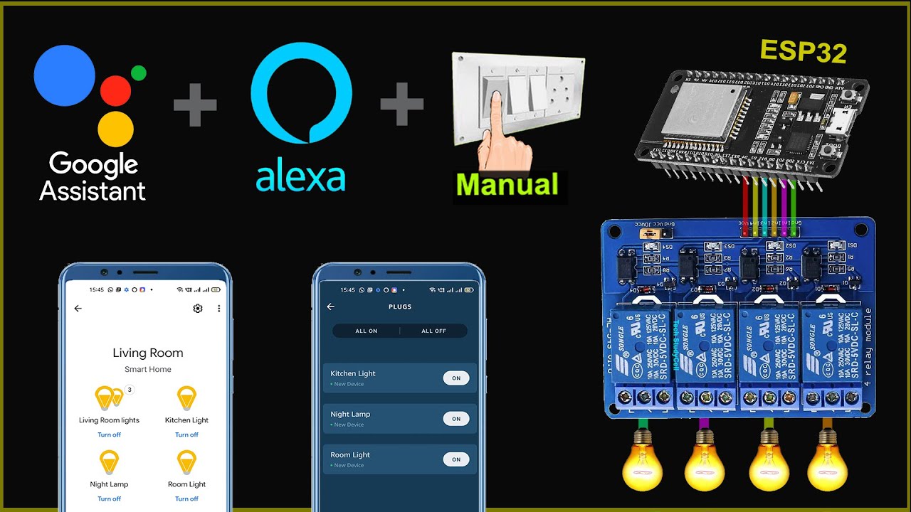
ESP32 Home automation with Google Assistant Alexa & Manual Switches - Internet of Things 2021
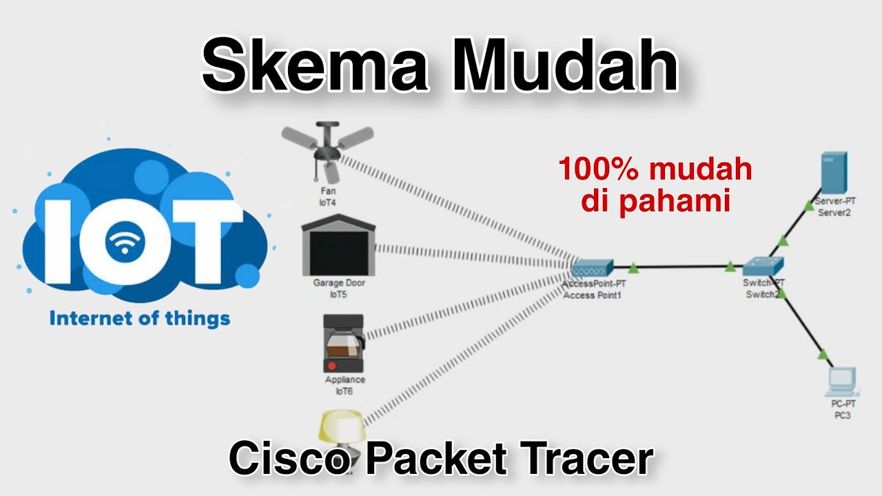
Konfigurasi IoT Perangkat Smart Home - Internet of Things | Cisco Packet Tracer

ESP8266 RFID Attendance System with Google Sheets

Mengimplementasi IoT pada Smart home | Simulasi menggunakan Cisco Packet Tracer
5.0 / 5 (0 votes)