cara membuat simulasi VPN server menggunakan cisco packet tracer
Summary
TLDRThis tutorial demonstrates how to simulate a VPN using Cisco Packet Tracer. The setup includes three routers and two PCs, where the network configuration process involves connecting routers and PCs, assigning IP addresses, and configuring Ethernet interfaces. Detailed steps are followed for each device, ensuring successful IP setup for communication between the devices. The tutorial also highlights troubleshooting with ping tests to ensure proper connectivity between the routers and PCs. The video concludes with the confirmation of a successful VPN simulation setup, allowing for practical understanding of Cisco Packet Tracer configurations.
Takeaways
- 😀 Devices used in the simulation include 3 routers and 2 PCs (PC1 and PC2).
- 😀 The routers are named 'Router1', 'Router2', and 'Router', while the PCs are named 'PC1' and 'PC2'.
- 😀 The first step in the setup is arranging and connecting the devices properly in the Cisco Packet Tracer workspace.
- 😀 Connections between devices are made using cables, with specific ports on routers like FastEthernet0 and FastEthernet1 being utilized.
- 😀 IP addresses are manually configured for each device, starting with 'Router1' at '192.168.1.1'.
- 😀 PC1 is assigned IP '192.168.1.2' with '192.168.1.1' as its default gateway.
- 😀 Router2 is configured with IP '192.168.2.1' and PC2 gets IP '192.168.2.2' with '192.168.2.1' as the gateway.
- 😀 The top router gets IPs '1.0.0.1' (FastEthernet0) and '2.0.0.1' (FastEthernet1).
- 😀 After configuring the IP addresses, routers and interfaces must be enabled using the 'no shutdown' command.
- 😀 A ping test is performed to verify the connectivity between the devices, ensuring proper network setup and configuration.
Q & A
What is the primary goal of this Cisco Packet Tracer simulation?
-The primary goal is to simulate a VPN configuration using multiple routers and PCs in Cisco Packet Tracer.
How many routers and PCs are involved in this simulation?
-The simulation involves 3 routers and 2 PCs.
What is the naming convention for the PCs in this simulation?
-The PCs are named PC1 and PC2 for easy identification, with PC1 on the left and PC2 on the right.
What type of cable is used to connect the devices in this simulation?
-Ethernet cables are used to connect the devices, such as between the PCs and routers.
What IP address is configured on Router 1 for FastEthernet 0?
-Router 1 is configured with the IP address 192.168.1.1 on FastEthernet 0.
What is the default gateway IP configured on PC1?
-The default gateway IP for PC1 is set to 192.168.1.1.
What IP address is assigned to PC2 in this simulation?
-PC2 is assigned the IP address 192.168.2.2.
What is the IP address configured on Router 2 for FastEthernet 0?
-Router 2 is configured with the IP address 192.168.2.1 on FastEthernet 0.
What is the purpose of enabling the 'on' setting in the router configuration?
-Enabling the 'on' setting ensures that the interface is activated and ready to pass traffic.
How does the simulation test connectivity between the devices?
-The connectivity between the devices is tested by using the 'ping' command in the command prompt to verify communication between the PCs and routers.
Outlines

This section is available to paid users only. Please upgrade to access this part.
Upgrade NowMindmap

This section is available to paid users only. Please upgrade to access this part.
Upgrade NowKeywords

This section is available to paid users only. Please upgrade to access this part.
Upgrade NowHighlights

This section is available to paid users only. Please upgrade to access this part.
Upgrade NowTranscripts

This section is available to paid users only. Please upgrade to access this part.
Upgrade NowBrowse More Related Video

Jaringan Komputer Sederhana | Tutorial Belajar Online Lengkap CISCO CCNA 200-301 Part 5

Basics of Cisco Packet Tracer (Part 2) | Hub
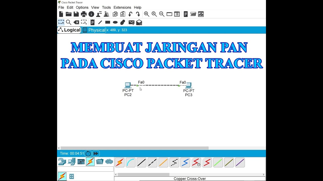
Membuat Jaringan PAN pada Cisco Packet Tracer

Netzwerktutorial: Cisco Packet Tracer - Installation, Konfiguration & ein erster Aufbau
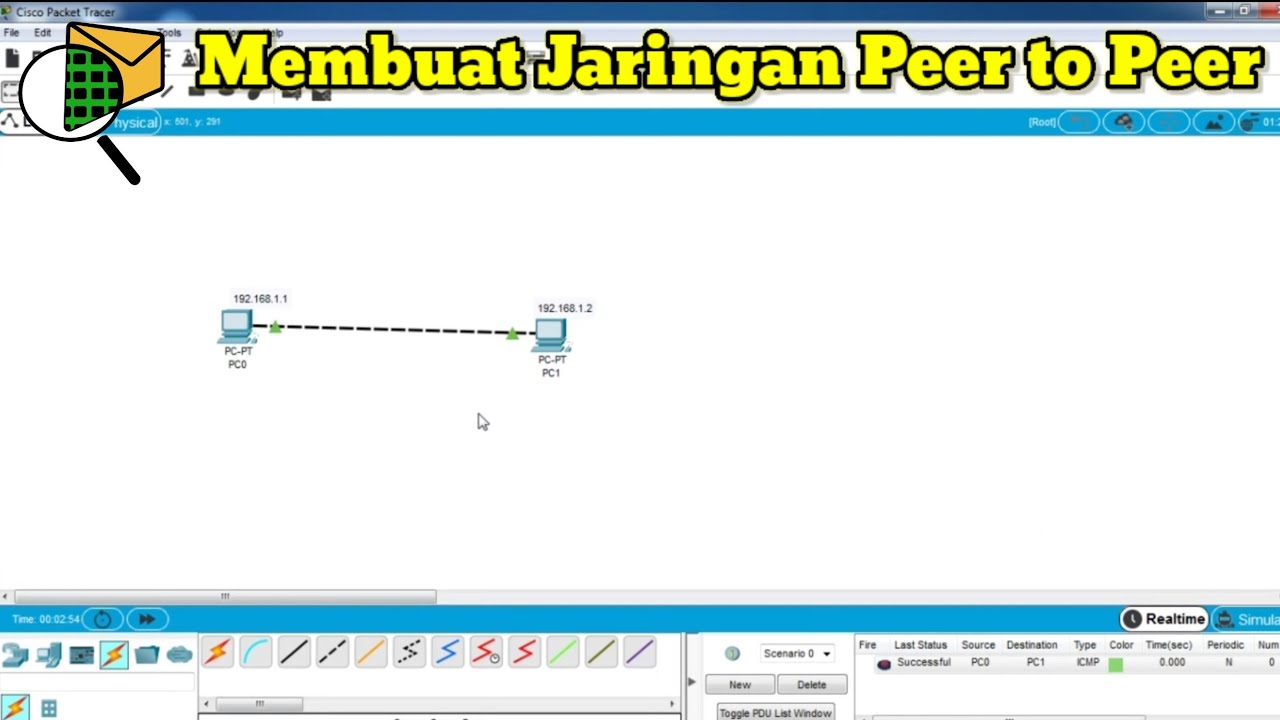
Cara Membuat Jaringan Peer To Peer di Cisco Packet Tracer
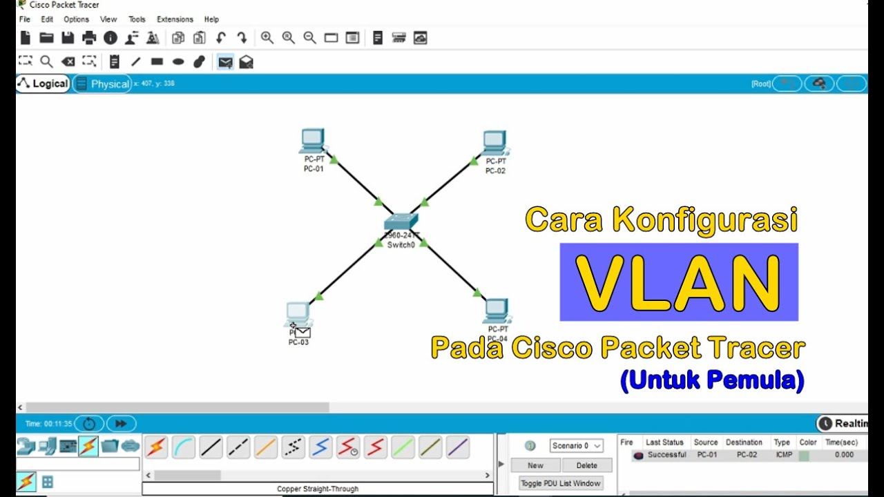
Tutorial - Cara Konfigurasi VLAN pada Cisco Packet Tracer (Untuk Pemula)
5.0 / 5 (0 votes)