AC Through Series RLC Circuit - AC Circuits - Basic Electrical Engineering
Summary
TLDRIn this video, the relationship between AC voltage and a series connection of passive elements—resistors, capacitors, and inductors—is explored. The presenter illustrates how current and power behave in different circuit configurations, examining the impact of inductive and capacitive reactance. Through detailed phasor diagrams and voltage triangles, three distinct scenarios are analyzed: when inductive reactance dominates, when capacitive reactance prevails, and when both are equal, resulting in a purely resistive circuit. The video concludes by emphasizing the significance of understanding these relationships in electrical circuits.
Takeaways
- 🔌 The video explains the effects of applying AC voltage to a series connection of passive components: resistance (R), capacitance (C), and inductance (L).
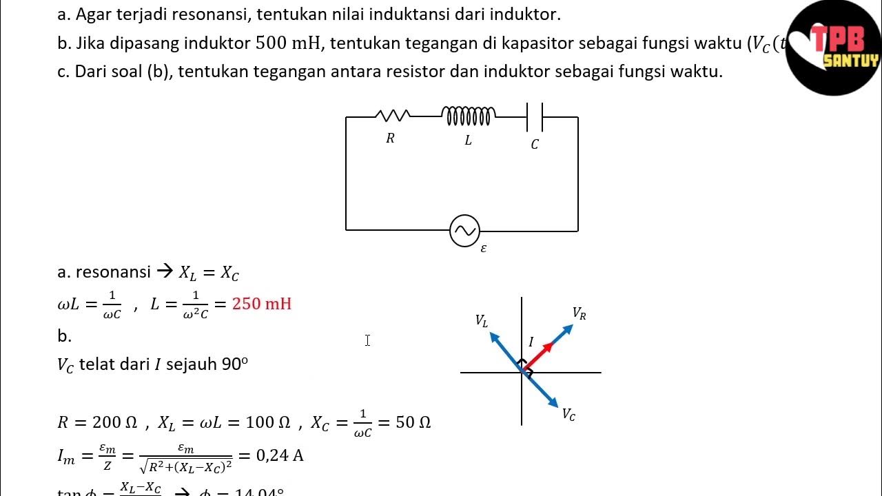
- 📊 The current (I) in the circuit is responsible for three voltage drops: across resistance (V_R), inductance (V_L), and capacitance (V_C).
- ⚡ The voltage drop across resistance is directly proportional to the current (V_R = I × R).
- 🔋 The inductive voltage drop is given by V_L = I × X_L, where X_L is the inductive reactance (2πfL).
- 🔄 The capacitive voltage drop is given by V_C = I × X_C, where X_C is the capacitive reactance (1/(2πfC)).
- 📈 When X_L > X_C, the circuit is inductive, with the total voltage dominated by the inductive component.
- 📉 When X_C > X_L, the circuit is capacitive, with the total voltage dominated by the capacitive component.
- ⚖️ When X_L equals X_C, the voltage drops across the inductor and capacitor cancel each other, resulting in a purely resistive circuit.
- 🔺 The phasor diagrams for inductive and capacitive circuits show that voltage and current are out of phase by 90 degrees.
- ⚙️ The power triangle for the circuit varies depending on the nature of the circuit (inductive, capacitive, or resistive), reflecting the relationships among active, reactive, and apparent power.
Q & A
What is the nature of the current when AC voltage is applied to a series RLC circuit?
-The nature of the current in a series RLC circuit depends on the relationship between the inductive reactance (X_L) and capacitive reactance (X_C). It can be inductive, capacitive, or purely resistive.
How are the voltage drops across each component in a series RLC circuit calculated?
-The voltage drops across each component are calculated as follows: across the resistor (V_R = I * R), across the inductor (V_L = I * X_L), and across the capacitor (V_C = I * X_C).
What happens to the circuit's nature when X_L is greater than X_C?
-When X_L is greater than X_C, the circuit is inductive in nature, with the total voltage dominated by the inductor, resulting in a phase angle where the voltage leads the current.
What are phasor diagrams, and how do they represent the relationship between voltage and current?
-Phasor diagrams are graphical representations of the relationships between voltage and current in AC circuits. They illustrate the phase differences, showing how the current and voltage waveforms relate to one another in terms of leading or lagging.
In an RLC circuit, what occurs when X_C is greater than X_L?
-When X_C is greater than X_L, the circuit is capacitive in nature. This means the voltage drop across the capacitor dominates, causing the voltage to lag behind the current.
What is the significance of the condition when X_L equals X_C?
-When X_L equals X_C, the voltage drops across the inductor and capacitor cancel each other out. The circuit behaves as purely resistive, and the current and voltage are in phase, with a phase angle of zero degrees.
How are the power triangles affected in inductive and capacitive circuits?
-In an inductive circuit, the power triangle includes active power (P), reactive power (Q), and apparent power (S), with an associated phase angle. In a capacitive circuit, the power triangle also represents P, Q, and S but reflects the characteristics of a capacitive load.
What formulas are used to determine the reactance for inductors and capacitors?
-Inductive reactance (X_L) is calculated using the formula X_L = 2πfL, while capacitive reactance (X_C) is calculated as X_C = 1 / (2πfC).
How does the total voltage in a series RLC circuit relate to the individual voltage drops?
-The total voltage in a series RLC circuit is the vector sum of the individual voltage drops across the resistor, inductor, and capacitor. This requires considering the phase relationships of each voltage drop.
What can be concluded about the behavior of a series RLC circuit under different conditions?
-The behavior of a series RLC circuit can vary significantly based on the relationship between X_L and X_C. Depending on whether the circuit is inductive, capacitive, or resistive, different voltage and current characteristics are observed.
Outlines

This section is available to paid users only. Please upgrade to access this part.
Upgrade NowMindmap

This section is available to paid users only. Please upgrade to access this part.
Upgrade NowKeywords

This section is available to paid users only. Please upgrade to access this part.
Upgrade NowHighlights

This section is available to paid users only. Please upgrade to access this part.
Upgrade NowTranscripts

This section is available to paid users only. Please upgrade to access this part.
Upgrade NowBrowse More Related Video

Resistive circuits in series

Electrical Engineering: Ch 8: RC & RL Circuits (1 of 43) RC & RL Circuits Introduction
Analisis Rangkaian AC | Rangkaian AC | Part 3 | Fisika Dasar
AC Circuits: Crash Course Physics #36

Electrical Engineering: Basic Concepts (7 of 7) Passive vs Active Elements

Simulasi Arus dan Tegangan Bolak-Balik dengan Phet
5.0 / 5 (0 votes)