Resistive circuits in series
Summary
TLDRThis video provides an introduction to electrical circuits, focusing on resistive circuits. It explains how current flows through resistors in series, the relationship between voltage, current, and resistance, and the application of Ohm's law. The concept of voltage drops across resistors is explored, emphasizing conservation of charge and energy. The video also covers the calculation of equivalent resistance in series circuits and prepares the viewer for future lessons on parallel resistors and more complex circuits involving inductors and capacitors.
Takeaways
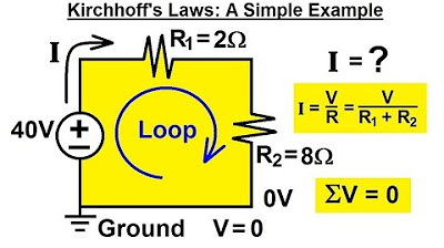
- 😀 Resistor circuits involve elements with different resistances, such as R1 and R2, and they create electric fields when connected in a conducting material.
- 😀 Voltage (ΔV) is the result of an electric field between two plates, which can cause a current to flow when a conducting circuit is created.
- 😀 Current (I) is conserved throughout the circuit, meaning the current that flows into one part of the circuit equals the current that flows out of it.
- 😀 Conservation of charge and energy is key: the total voltage difference around a closed loop must sum to zero, meaning no net work is done in the system.
- 😀 Integrating the electric field around the closed loop (in a non-time-dependent situation) gives zero, which is another way to express energy conservation in the circuit.
- 😀 Voltage across different components in the circuit must sum to zero, meaning that the individual voltages across resistors must add up to the total voltage difference.
- 😀 If each resistor follows Ohm's law, the voltage across each can be represented by Ohm's law (V = IR), where I is the current and R is resistance.
- 😀 In a resistive circuit with resistors in series, the voltage across each resistor adds up, and the total resistance is the sum of the individual resistances.
- 😀 The equivalent resistance of resistors in series is the sum of the individual resistances, which simplifies the analysis of the circuit.
- 😀 The next topic to be covered will be the behavior of resistors in parallel, which is different from resistors in series.
- 😀 This lecture forms the foundation for more complex circuits, which will include combinations of resistors, capacitors, and inductors.
Please replace the link and try again.
Outlines

This section is available to paid users only. Please upgrade to access this part.
Upgrade NowMindmap

This section is available to paid users only. Please upgrade to access this part.
Upgrade NowKeywords

This section is available to paid users only. Please upgrade to access this part.
Upgrade NowHighlights

This section is available to paid users only. Please upgrade to access this part.
Upgrade NowTranscripts

This section is available to paid users only. Please upgrade to access this part.
Upgrade NowBrowse More Related Video
Electrical Engineering: Basic Laws (9 of 31) Kirchhoff's Laws: A Simple Example

Basic Electrical Engineering | Module 3 | Syllabus Overview of Three Phase AC Circuits (Lecture 19)

Listrik Dinamis-Rangkaian Listrik (Hukum Ohm) (Part 3)
Electronic and Circuits Week 1 Lecturer || Basic Concepts of Electronic Circuit
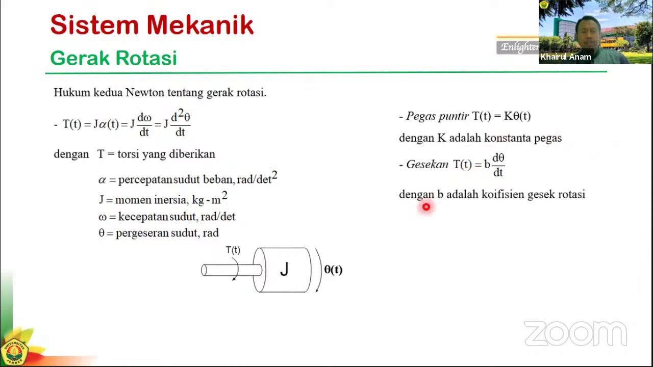
SK#2c: Pemodelan Sistem dengan Persamaan Differensial

More Essentials about Circuits
5.0 / 5 (0 votes)