AC Circuits: Crash Course Physics #36
Summary
TLDRThis video explores the physics of alternating current (AC) circuits, focusing on how resistors, capacitors, and inductors interact within these systems. Unlike direct current (DC), AC involves constantly changing voltage and current, which can be described using RMS values. The video explains key concepts such as self-inductance, phase differences between voltage and current in various components, and how these affect overall circuit behavior. Viewers will learn how to analyze circuits with multiple components and gain insight into the relationship between electricity, electromagnetism, and light.
Takeaways
- 😀 Alternating current (AC) circuits involve voltage and current that constantly change direction, unlike direct current (DC) circuits where the current is constant.
- 😀 In AC circuits, peak current and voltage values represent the maximum positive and negative values that the current and voltage reach during each cycle.
- 😀 RMS (Root Mean Square) values are used to represent effective current and voltage in AC circuits, allowing the use of DC formulas in AC calculations.
- 😀 The RMS current is the value you would get by squaring the current, averaging it, and then square rooting it. It's a way to express fluctuating current in a stable form.
- 😀 In an AC circuit, inductors oppose changes in current due to induced electromotive force (emf), following Lenz's Law.
- 😀 The induced emf in an inductor is calculated as the negative product of inductance (L) and the rate of change in current, which can delay changes in current over time.
- 😀 An inductor in a DC circuit causes the current to gradually increase or decrease, depending on whether the voltage source is applied or removed.
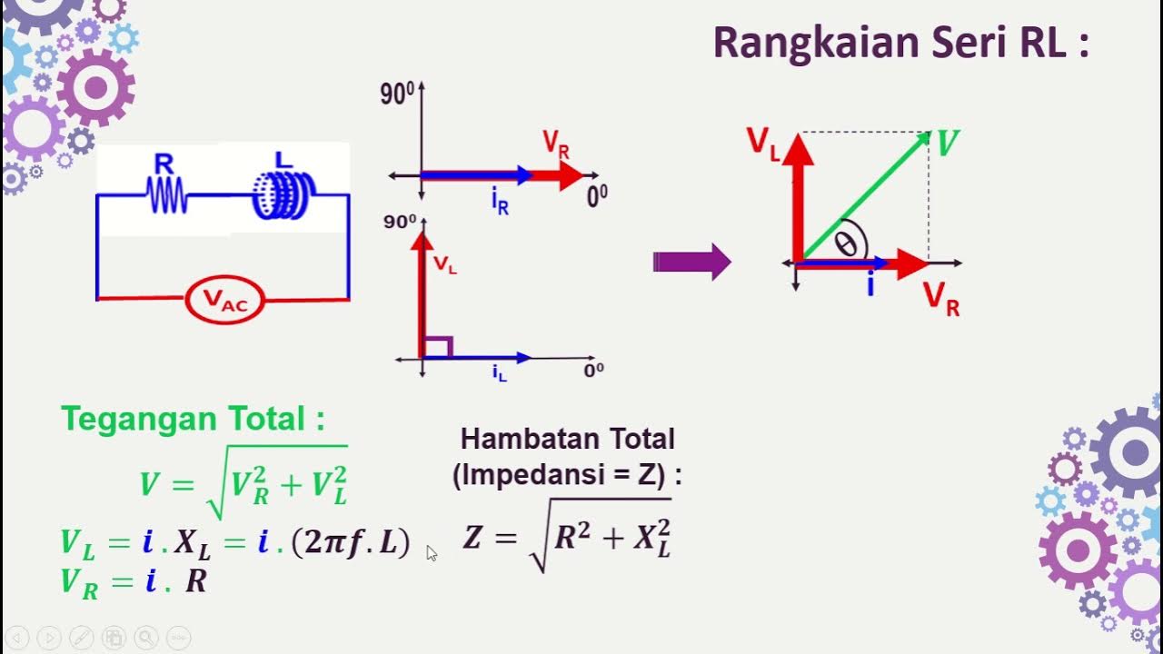
- 😀 In AC circuits, resistors allow current to pass with voltage and current in phase, meaning they peak simultaneously.
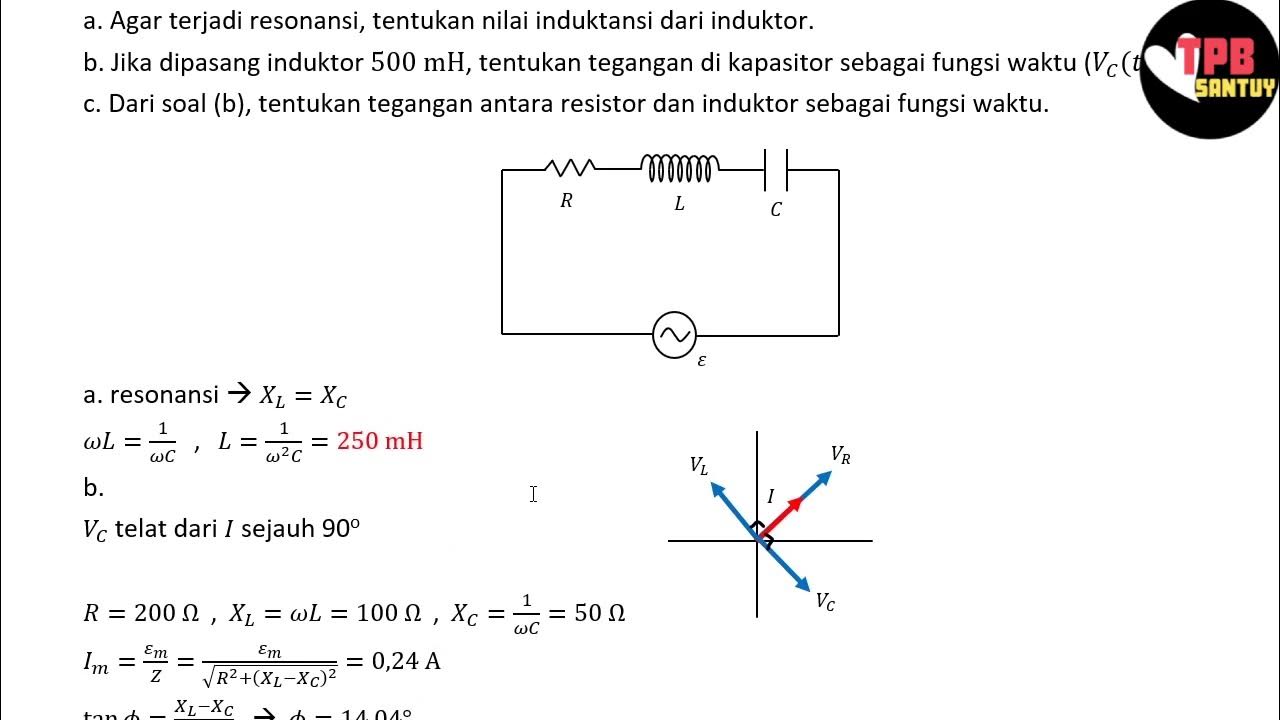
- 😀 Capacitors in AC circuits cause current to lead voltage by 90 degrees, meaning current reaches its peak before voltage does.
- 😀 In AC circuits with inductors, capacitors, and resistors in series, each component causes a phase shift in current and voltage, but the total voltage drops across all components equal the total applied voltage.
- 😀 Inductors and capacitors do not dissipate power as heat like resistors; they store and release energy in the circuit, affecting the voltage but not consuming it.
Q & A
What is the main purpose of alternating currents (AC)?
-The main purpose of alternating currents (AC) is to transmit electricity over long distances efficiently by changing the voltage, which allows it to travel with less energy loss compared to direct current (DC).
How does the current behave in an AC circuit compared to a DC circuit?
-In a DC circuit, the current is constant because the voltage does not change. In an AC circuit, both the voltage and current change directions continuously, alternating between positive and negative values.
What is the root-mean-square (RMS) value, and why is it used in AC circuits?
-The RMS value is an effective value of alternating current or voltage that represents the equivalent DC value. It is calculated by squaring the current or voltage, averaging it, and then taking the square root. RMS is used to simplify AC calculations by allowing the use of DC power formulas.
How is the average power consumed in an AC circuit calculated?
-The average power in an AC circuit is calculated using the RMS values of current and voltage. The power formula is similar to DC circuits, with the RMS current and voltage replacing the peak current and voltage, and the average power is given by the product of RMS current and RMS voltage.
What is Lenz's Law, and how does it relate to inductors in AC circuits?
-Lenz's Law states that the direction of the induced electromotive force (emf) in a conductor is such that it opposes the change in current. In AC circuits, this law explains how an inductor generates an opposing emf to resist changes in current, leading to self-inductance.
How do inductors behave in a DC circuit compared to an AC circuit?
-In a DC circuit, inductors oppose sudden changes in current, gradually increasing until the current reaches its maximum value. In an AC circuit, inductors cause the current to lag behind the voltage by 90 degrees due to the opposition of the changing current by the induced emf.
What is the role of the time constant (τ) in an LR circuit?
-The time constant (τ) in an LR circuit determines how quickly the current reaches its maximum value. It is the ratio of inductance (L) to resistance (R), and it influences how fast the current builds up or decreases over time when the voltage is applied or removed.
What happens when the battery is removed from an LR circuit after it reaches a steady state?
-When the battery is removed from an LR circuit, the inductor generates its own current to oppose the sudden change in current, causing the current to decrease gradually instead of stopping immediately, similar to how a car slows down after releasing the accelerator.
How do capacitors behave differently from inductors in AC circuits?
-In an AC circuit, capacitors cause the current to lead the voltage by 90 degrees because they momentarily store charge as the voltage changes direction, whereas inductors cause the current to lag behind the voltage due to the opposing emf.
How does the combination of a resistor, inductor, and capacitor in series affect voltage in an AC circuit?
-In a series AC circuit with a resistor, inductor, and capacitor, the voltage across each component peaks at different times. The sum of these voltage drops equals the total voltage supplied by the source, though each component contributes differently due to their phase relationships with current.
Outlines

This section is available to paid users only. Please upgrade to access this part.
Upgrade NowMindmap

This section is available to paid users only. Please upgrade to access this part.
Upgrade NowKeywords

This section is available to paid users only. Please upgrade to access this part.
Upgrade NowHighlights

This section is available to paid users only. Please upgrade to access this part.
Upgrade NowTranscripts

This section is available to paid users only. Please upgrade to access this part.
Upgrade NowBrowse More Related Video
5.0 / 5 (0 votes)


