Low Pass Filters and High Pass Filters - RC and RL Circuits
Summary
TLDRThis video explains the concepts of low-pass and high-pass filters, detailing their functionality and circuit designs. It covers the RC and RL low-pass filters, emphasizing how they allow low-frequency signals to pass while attenuating high-frequency signals. The video also describes high-pass filters, illustrating how they permit high frequencies to pass while blocking low frequencies. Key formulas for cutoff frequency and output voltage are provided, along with graphical representations of frequency responses. Overall, it offers a foundational understanding of filter circuits and their applications in signal processing.
Takeaways
- 🎛️ Low pass filters allow low-frequency signals to pass while greatly reducing the amplitude of high-frequency signals.
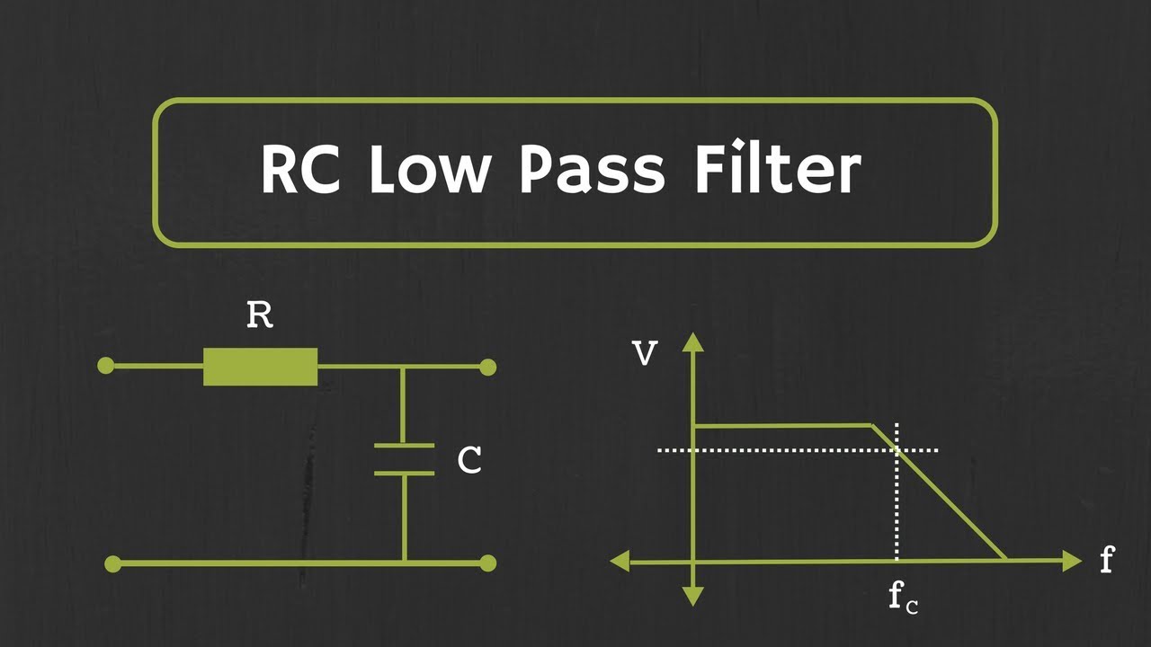
- 🔌 An RC low pass filter consists of a resistor and a capacitor, where the output voltage is affected by the values of these components.
- 📉 The cutoff frequency (fc) of an RC low pass filter is calculated using the formula fc = 1/(2πRC), where R is resistance and C is capacitance.
- 📊 At the cutoff frequency, the output voltage is 70.7% of the input voltage, corresponding to a 3 dB drop in decibels.
- 🔄 Capacitive reactance (Xc) decreases as frequency increases, allowing high-frequency signals to pass through while blocking low frequencies.
- 📈 In RL low pass filters, the output voltage is high when frequency is low, allowing low frequencies to pass while impeding high frequencies.
- 🧮 The cutoff frequency for RL filters is determined by the formula fc = R/(2πL), where R is resistance and L is inductance.
- 🎚️ High pass filters allow high-frequency signals to pass through while blocking low-frequency signals, functioning oppositely to low pass filters.
- ⚡ In RC high pass filters, the capacitor is positioned to allow high frequencies to pass and blocks low frequencies, with the output voltage influenced by the capacitive reactance.
- 🔄 The RL high pass filter allows high-frequency signals to pass while blocking low frequencies due to the properties of inductance.
Q & A
What is the primary function of a low pass filter?
-A low pass filter allows low-frequency signals to pass through unimpeded while attenuating high-frequency signals by reducing their amplitude.
How does the amplitude of high-frequency signals change in a low pass filter?
-In a low pass filter, the amplitude of high-frequency signals is significantly reduced, meaning they are blocked or greatly attenuated.
What is the key difference between an RC low pass filter and an RL low pass filter?
-In an RC low pass filter, the capacitor blocks high-frequency signals, while in an RL low pass filter, the inductor blocks high-frequency signals.
How is the cutoff frequency calculated for an RC low pass filter?
-The cutoff frequency (Fc) for an RC low pass filter is calculated using the formula: Fc = 1 / (2πRC), where R is the resistance and C is the capacitance.
At the cutoff frequency of an RC low pass filter, what percentage of the input voltage remains at the output?
-At the cutoff frequency of an RC low pass filter, the output voltage will be 70.7% of the input voltage.
What role does capacitive reactance play in a low pass filter?
-Capacitive reactance (Xc) acts like resistance for AC signals, decreasing as the frequency increases, thus allowing high-frequency signals to pass through while blocking low-frequency signals.
What happens to the output voltage in an RL low pass filter when the frequency increases?
-In an RL low pass filter, as the frequency increases, the inductive reactance increases, which causes the output voltage to decrease.
How is the cutoff frequency calculated for an RL low pass filter?
-The cutoff frequency (Fc) for an RL low pass filter is calculated using the formula: Fc = R / (2πL), where R is the resistance and L is the inductance.
What is the key difference between a low pass filter and a high pass filter?
-A low pass filter allows low-frequency signals to pass and blocks high-frequency signals, while a high pass filter allows high-frequency signals to pass and blocks low-frequency signals.
In a high pass filter, what happens to the output voltage as the frequency increases?
-In a high pass filter, as the frequency increases, the output voltage increases, eventually approaching the input voltage as the frequency goes to infinity.
Outlines

This section is available to paid users only. Please upgrade to access this part.
Upgrade NowMindmap

This section is available to paid users only. Please upgrade to access this part.
Upgrade NowKeywords

This section is available to paid users only. Please upgrade to access this part.
Upgrade NowHighlights

This section is available to paid users only. Please upgrade to access this part.
Upgrade NowTranscripts

This section is available to paid users only. Please upgrade to access this part.
Upgrade NowBrowse More Related Video
Electronics 101: Active Filters
RC Low Pass Filter Explained

Pengolahan Sinyal Digital: 11 Tipe dan Karakteristik Filter

First Order RC Low Pass Filter | Construction, Working, Cut Off Frequency Derivation | Simplified |

Butterworth Filter : Design of Low Pass and High Pass Filters

Konsep dan Parameter Filter (Video 2.6)
5.0 / 5 (0 votes)