Butterworth Filter : Design of Low Pass and High Pass Filters
Summary
TLDRThis video delves into the design of Butterworth filters, focusing on both low pass and high pass configurations using the Sallen-Key topology. The presenter explains the theory behind the Butterworth approximation, highlighting the flat passband and its roll-off rate. It covers the step-by-step process of designing second, third, and higher-order Butterworth filters and the key factors like the quality factor (Q) for achieving a smooth response. Additionally, the video touches on practical exercises for filter design, offering a detailed explanation of the required components and formulas for creating both low pass and high pass filters.
Takeaways
- 😀 The Butterworth filter has a flat passband and a roll-off of 20n dB per decade. For example, a 4th-order filter has a roll-off of 80 dB per decade.
- 😀 The transfer function of a second-order low pass filter can be written in terms of gain (k), cutoff frequency (omega_n), and quality factor (Q).
- 😀 Cascading two first-order low-pass filters cannot design a Butterworth filter because it requires a higher quality factor (Q).
- 😀 The Sallen-Key filter topology is commonly used for Butterworth filter design, providing positive feedback and active components.
- 😀 The quality factor (Q) represents the amount of peaking around the cutoff frequency. For Butterworth design, Q is 0.707.
- 😀 By adjusting the gain (k) in the Sallen-Key filter, you can control the quality factor (Q) and design a Butterworth filter with the desired properties.
- 😀 The design of the Butterworth low-pass filter requires a specific gain (k), with k = 1.586 for the standard Butterworth filter with Q = 0.707.
- 😀 The Butterworth filter can be cascaded with multiple second-order filters to create higher-order filters for better roll-off performance.
- 😀 The polynomials used for second-order low-pass Butterworth filters can be applied to design higher-order filters with a desired cutoff frequency.
- 😀 The process for designing Butterworth high-pass filters is similar to low-pass filters, except the positions of resistors and capacitors are interchanged.
Q & A
What is a Butterworth filter and what is its key characteristic?
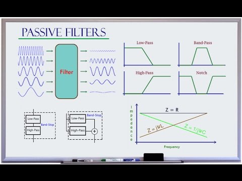
-A Butterworth filter is a type of signal processing filter known for having a maximally flat passband. Its key characteristic is that the roll-off rate is 20n dB per decade, where 'n' is the filter order.
How does the roll-off rate change for different order filters in Butterworth design?
-The roll-off rate in a Butterworth filter increases with the filter order. For example, a 4th order filter has a roll-off of 80 dB per decade, and an 8th order filter has a roll-off of 160 dB per decade.
What is the formula for the transfer function of a second-order low-pass filter?
-The transfer function of a second-order low-pass filter is given by k * ωc² / (s² + (2/RC)s + ωc²), where k is the gain, ωc is the cutoff frequency, and RC is the product of resistance and capacitance.
Why does cascading first-order filters not work for designing a Butterworth filter?
-Cascading first-order filters does not work for designing a Butterworth filter because it doesn't provide the necessary value of the quality factor (Q). The Butterworth design requires a Q of 0.707, which is achieved through active components and positive feedback.
What is the role of the quality factor (Q) in a Butterworth filter design?
-The quality factor (Q) in a Butterworth filter determines the amount of peaking around the cutoff frequency. A Q value of 0.707 ensures the filter has a maximally flat passband with no peaking at the cutoff frequency.
How is the quality factor (Q) calculated in a Sallen-Key low-pass filter?
-In a Sallen-Key low-pass filter, the quality factor (Q) can be calculated using the formula Q = 1 / (3 - k), where k is the gain. The value of k should be less than 3 to maintain system stability.
How do you determine the value of 'k' for a Butterworth filter design using a Sallen-Key topology?
-The value of 'k' for a Butterworth filter design is determined by the equation 1.414 = 3 - k. Solving this gives k = 1.586, which is used to calculate component values in the design.
What is the importance of the feedback network in a Sallen-Key filter for Butterworth design?
-The feedback network in a Sallen-Key filter allows for positive feedback, which is necessary to achieve the required Q value for Butterworth filter design. Without it, you cannot achieve the flat passband required for a Butterworth filter.
How do you design a third-order Butterworth low-pass filter?
-To design a third-order Butterworth low-pass filter, you cascade a second-order Sallen-Key Butterworth filter with a first-order RC low-pass filter. This ensures the desired transfer function and cutoff frequency.
How does the design process differ when creating Butterworth high-pass filters compared to low-pass filters?
-The design process for Butterworth high-pass filters is similar to low-pass filters, except that you interchange the positions of the resistor and capacitor in the Sallen-Key topology to create a high-pass configuration.
Outlines

This section is available to paid users only. Please upgrade to access this part.
Upgrade NowMindmap

This section is available to paid users only. Please upgrade to access this part.
Upgrade NowKeywords

This section is available to paid users only. Please upgrade to access this part.
Upgrade NowHighlights

This section is available to paid users only. Please upgrade to access this part.
Upgrade NowTranscripts

This section is available to paid users only. Please upgrade to access this part.
Upgrade Now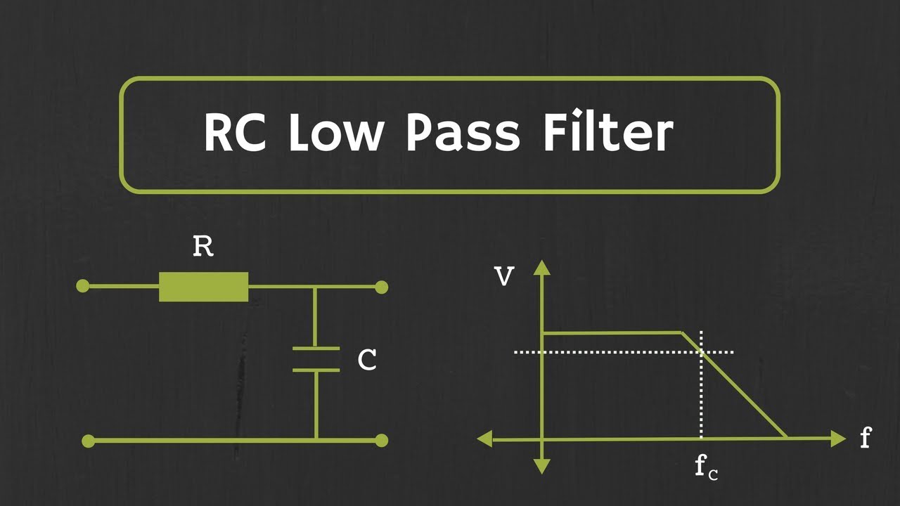


5.0 / 5 (0 votes)