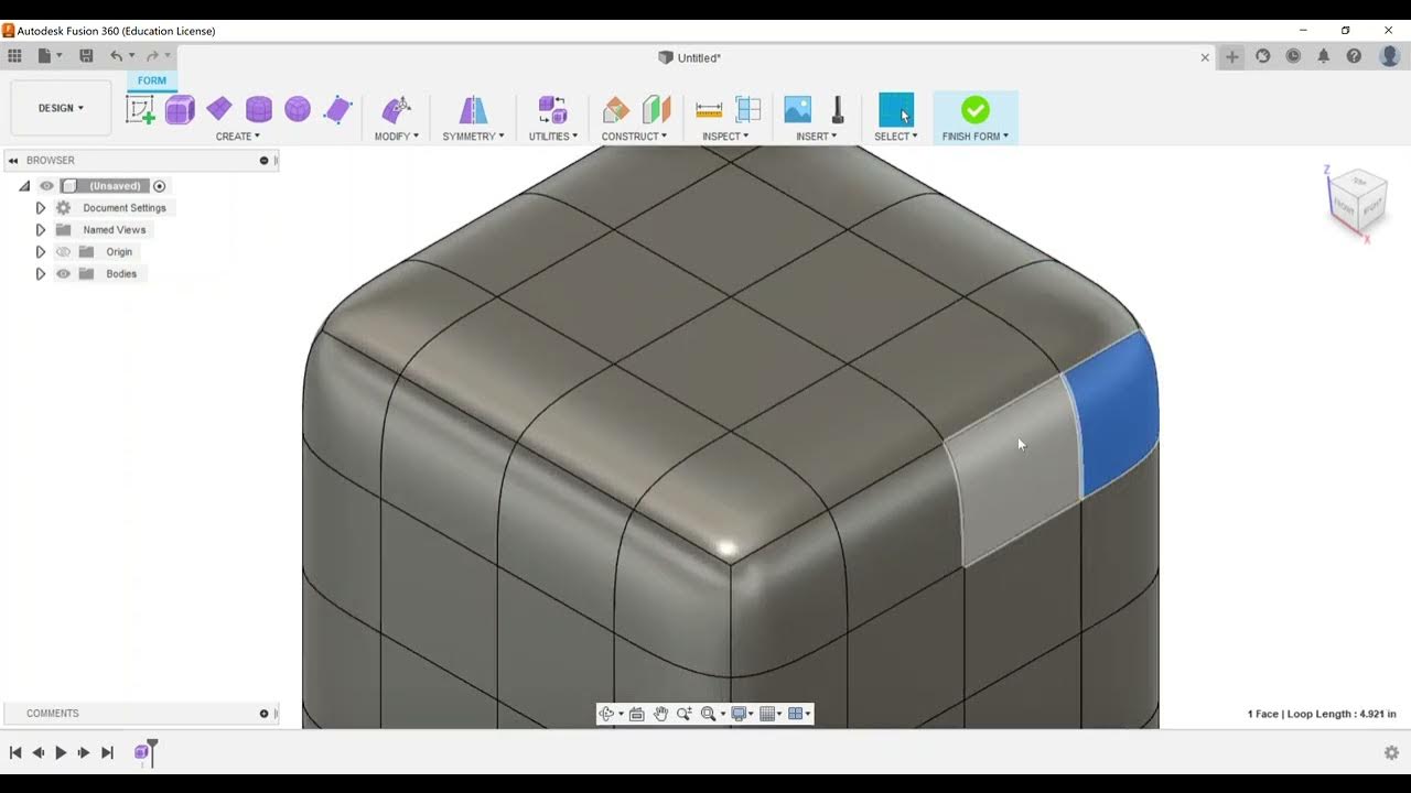
Part Modeling - Apply Fillets and Chamfers
Summary
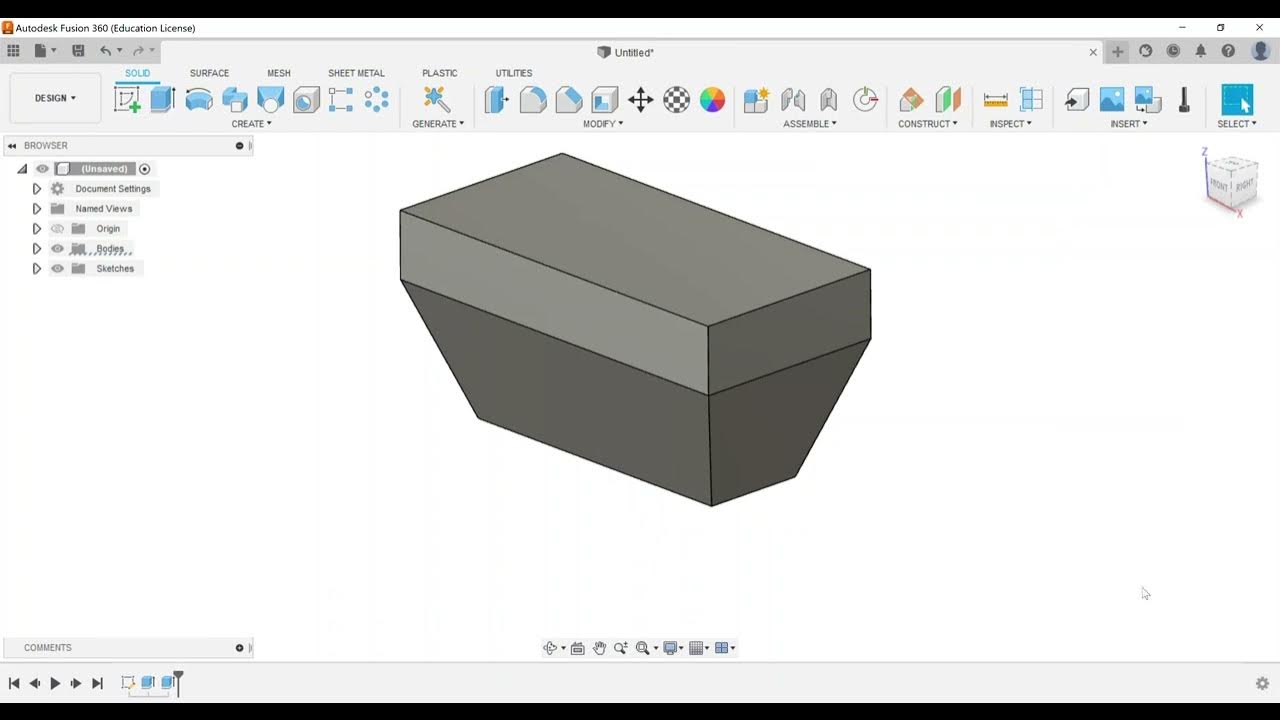
TLDRIn this instructional video, the presenter focuses on applying fillets and chamfers in Autodesk Fusion 360, essential for the Certified User Exam. They demonstrate creating 3D features and show the process in both 2D sketch and 3D modeling environments. The tutorial covers different types of chamfers and fillets, including equal distance, distance and angle, and two-distance chamfers. It also highlights the ease of editing these features in the modify panel versus the sketch environment and emphasizes the importance of understanding the order of selection for accurate angle references.
Takeaways
- 🔧 The video focuses on applying fillets and chamfers in Autodesk Fusion 360, which are crucial for part modeling.
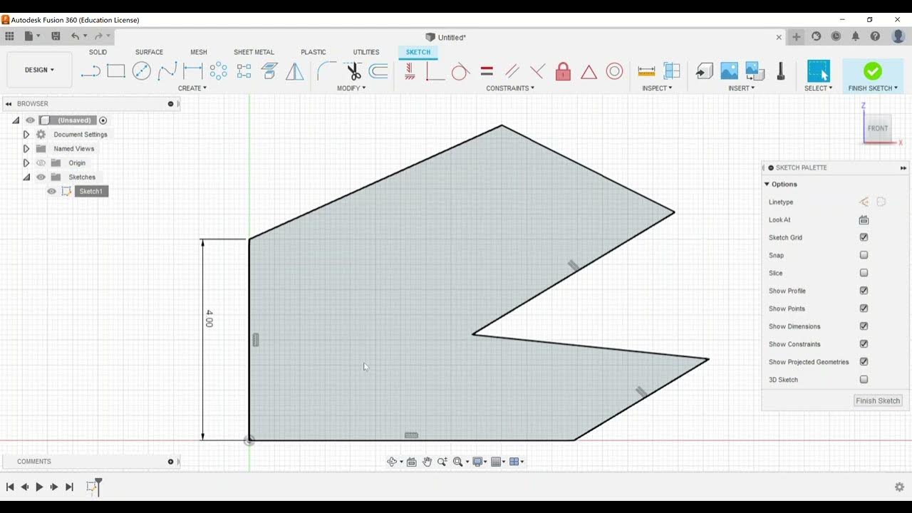
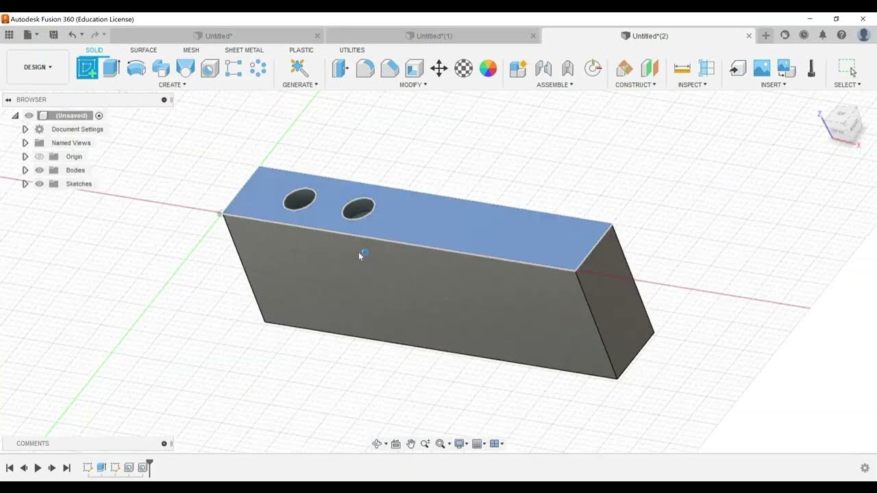
- 📐 It demonstrates how to create 3D features like fillets and chamfers, as well as their representation in the 2D sketch environment.
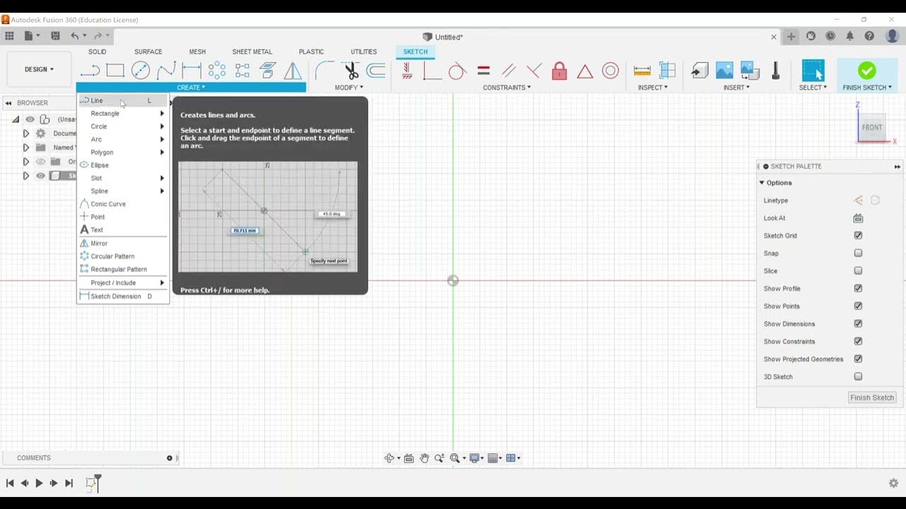
- 🛠️ The process starts by creating a sketch on the front work plane, drawing a rectangle with specific dimensions like 5 inches by 4 inches.
- ⚙️ Fillets are applied by selecting lines or arcs and setting a radius, which can be adjusted as needed, with potential warnings about constraint removal.
- 🔨 Chamfers are created with options for equal distance, distance and angle, or two distance chamfers, each requiring specific user inputs.
- 📏 When creating chamfers, the order of selection affects the angle reference, with the first line chosen setting the zero point.
- 🔄 The video emphasizes the importance of being able to edit these features easily in the modify panel compared to the sketch environment.
- 🔧 Tangency weight can be adjusted in fillets to create a more chamfered or rounded look, with options like tangent and curvature.
- 🔄 The 'rolling ball' is the most common corner type for fillets, but other options like 'setback' are also available.
- 📈 The video provides a step-by-step guide on how to apply these features, edit them if necessary, and understand the constraints and warnings that may appear.
- 📝 Lastly, the video encourages viewers to reach out with questions and explore more exam objectives for the Autodesk Fusion 360 Certified User Exam.
Q & A
What is the main focus of the video?
-The main focus of the video is to demonstrate how to apply fillets and chamfers in Autodesk Fusion 360, both in the 3D modeling environment and the 2D sketch environment.
What is the first step the presenter takes in the video?
-The first step the presenter takes is to create a sketch on the front work plane of Fusion 360.
What shape does the presenter draw in the sketch?
-The presenter draws a rectangle in the sketch.
What dimensions does the presenter give to the rectangle?
-The presenter gives the rectangle dimensions of 5 inches by 4 inches.
What does the presenter mean by 'Phillips' in the context of the video?
-In the context of the video, 'Phillips' refers to creating fillets, which are rounded corners in a 3D model.
How does the presenter apply a fillet in the 3D environment?
-The presenter applies a fillet by selecting an edge, specifying a radius, and then adjusting the tangency weight if necessary.
What are the three types of chamfers demonstrated in the video?
-The three types of chamfers demonstrated are equal distance chamfer, distance and angle chamfer, and two distance chamfer.
What is a warning message about constraints being removed during the chamfer or fillet operation?
-A warning message about constraints being removed indicates that the software has adjusted or removed some constraints to allow the new geometry to be created, which is not an error but a notification.
How can the presenter edit an existing fillet or chamfer?
-The presenter can edit an existing fillet or chamfer by right-clicking on the feature in the model history tree and selecting 'Edit the feature'.
What is the significance of the tangency weight when creating a fillet?
-The tangency weight affects the shape of the fillet, with higher values making it more rounded and lower values making it more like a chamfer.
How does the presenter demonstrate the difference between applying chamfers in the sketch environment versus the 3D modeling environment?
-The presenter demonstrates that applying chamfers in the 3D modeling environment allows for easier editing compared to the sketch environment, where constraints can be more complex to manage.
Outlines

This section is available to paid users only. Please upgrade to access this part.
Upgrade NowMindmap

This section is available to paid users only. Please upgrade to access this part.
Upgrade NowKeywords

This section is available to paid users only. Please upgrade to access this part.
Upgrade NowHighlights

This section is available to paid users only. Please upgrade to access this part.
Upgrade NowTranscripts

This section is available to paid users only. Please upgrade to access this part.
Upgrade Now5.0 / 5 (0 votes)
