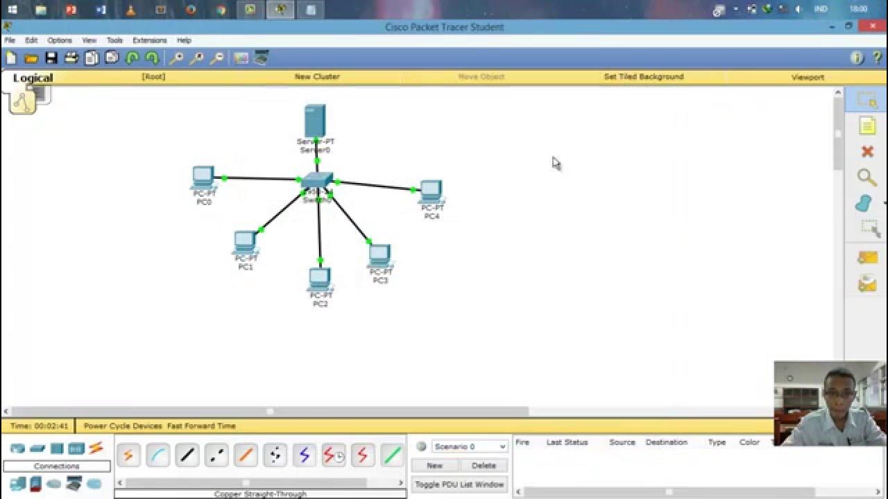
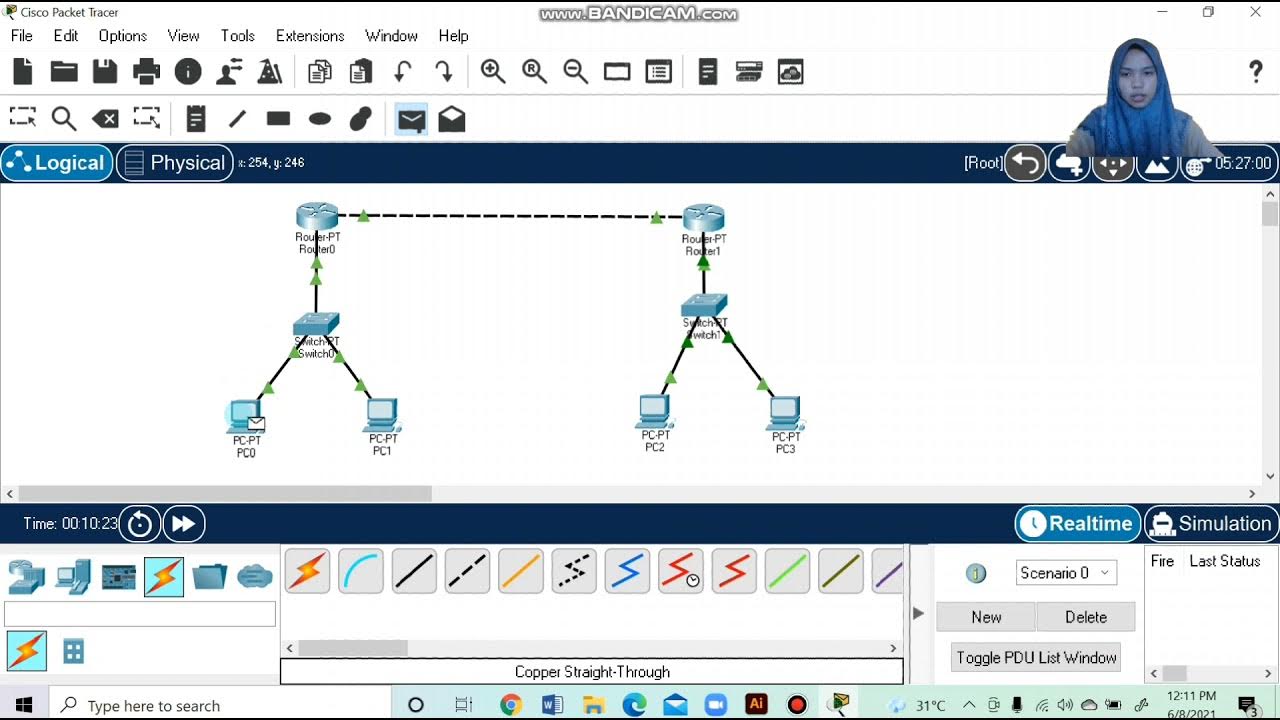
Konfigurasi DIAL UP dengan 2 ROUTER Cisco Packet Tracer
Summary
TLDRThis tutorial provides a step-by-step guide on configuring a dial-up network using Cisco Packet Tracer, involving two routers, a server, four clients, and modems. The video covers the setup of IP addresses, DHCP configurations for client devices, and the application of routing protocols like RIP to ensure proper connectivity. The presenter walks viewers through testing the network and troubleshooting issues to establish a functional connection. The setup is verified through successful pings and web access to the server, offering a comprehensive introduction to basic networking configuration and troubleshooting.
Takeaways
- 😀 The tutorial demonstrates how to configure a dial-up network in Cisco Packet Tracer, consisting of two routers, one server, two modems, and four clients (PCs and laptops).
- 😀 Routers, modems, and clients are connected using Ethernet and phone cables to create the network infrastructure.
- 😀 IP addresses are assigned to devices in the network, with class A IPs for routers and class C IPs for clients and the server.
- 😀 DHCP is set up on the routers to allocate IP addresses dynamically to the clients, ensuring proper network communication.
- 😀 Each client is configured with its unique IP settings using DHCP, ensuring all four clients can connect to the network.
- 😀 The server is configured with a static IP address, and its DNS settings are set to Google's DNS server for internet access.
- 😀 The routers are connected using routing protocols (RIP), ensuring data is correctly routed between devices in different subnets.
- 😀 The tutorial emphasizes the importance of checking and troubleshooting connectivity using ping tests from clients to routers and servers.
- 😀 The correct routing settings (RIP) are essential for successful communication between routers and clients over different network segments.
- 😀 After setting up the network and configuring all devices, the clients successfully connect to the server, and web access is tested successfully.
- 😀 The video concludes by highlighting the importance of correct configuration, testing, and troubleshooting to ensure a fully functional dial-up network in Cisco Packet Tracer.
Q & A
What is the purpose of the tutorial in the script?
-The tutorial demonstrates how to configure a simple dial-up network setup using Cisco Packet Tracer, involving two routers, a server, modems, and four clients.
What equipment is required for the configuration setup in the script?
-The configuration setup requires one server, two routers (Router 1 and Router 2), four clients (two PCs and two laptops), modems, and a cloud network.
How are the routers connected to the network in this configuration?
-The routers are connected using Ethernet cables, with each router having multiple Ethernet ports configured for different connections, including connections to the modems and other devices.
What specific IP address classes are used in the configuration?
-The IP address classes used are Class A and Class C. The first router uses IP addresses in the 12.x.x.x range, and the second router uses IP addresses in the 11.x.x.x range.
What role does the DHCP configuration play in the setup?
-DHCP is used to assign dynamic IP addresses to the clients. Each client is given a different range of IPs (10.10.0.x, 10.20.0.x, etc.) to ensure they are connected to the network correctly.
What is the significance of the 'rip' protocol mentioned in the script?
-The 'rip' protocol is used to share routing information between routers to ensure proper network connectivity. It is configured to declare the networks 10.x.x.x and 11.x.x.x on the routers.
What troubleshooting step is taken when connectivity fails?
-When connectivity fails, the routers are checked, and the 'rip' protocol is reconfigured to ensure proper routing between networks, resolving issues like the 'fail' message in pings.
How are DNS settings configured for the clients in this network?
-The DNS settings for the clients are configured to use Google's public DNS server (8.8.8.8) to enable proper name resolution.
What is the expected outcome when the configuration is correctly implemented?
-Once the configuration is complete and correct, all devices, including the clients, routers, and server, should be able to communicate with each other, and the web browser should successfully connect to the server.
Why is there a need to modify the power settings for certain devices like the routers and clients?
-The power settings for devices like routers, modems, and clients are modified to ensure proper initialization and to allow the addition of necessary ports before the devices are powered on again.
Outlines

Этот раздел доступен только подписчикам платных тарифов. Пожалуйста, перейдите на платный тариф для доступа.
Перейти на платный тарифMindmap

Этот раздел доступен только подписчикам платных тарифов. Пожалуйста, перейдите на платный тариф для доступа.
Перейти на платный тарифKeywords

Этот раздел доступен только подписчикам платных тарифов. Пожалуйста, перейдите на платный тариф для доступа.
Перейти на платный тарифHighlights

Этот раздел доступен только подписчикам платных тарифов. Пожалуйста, перейдите на платный тариф для доступа.
Перейти на платный тарифTranscripts

Этот раздел доступен только подписчикам платных тарифов. Пожалуйста, перейдите на платный тариф для доступа.
Перейти на платный тарифПосмотреть больше похожих видео

Konfigurasi Mudah DHCP SERVER di Cisco Packet Tracert dengan 1 Server 1 Switch 3 Client

SSH Configuration on Cisco Routers and Switches using Cisco Packet Tracer

Membuat Jaringan Sederhana dengan Cisco Packet Tracert | 1 Server 1 Router 2 Switch 6 Client

Cara Setting IP Dinamis menggunakan Cisco Packet Tracer #SMKTELKOMPWT

Topologi Jaringan Menghubungkan 2 Router 2 Switch dan 4 PC Packet Tracer

Cara Konfigurasi DNS Server Di Cisco Packet Tracer
5.0 / 5 (0 votes)
