Cara Menggambar dan Render 3D Bearing di AutoCAD
Summary
TLDRIn this tutorial, the host teaches how to draw a 3D bearing using AutoCAD. The video covers the entire process, starting with setting up the workspace and creating the base shapes, including rectangles, circles, and fillets. It explains how to manipulate and copy objects, add 3D elements, and apply revolutions to create the inner and outer rings of the bearing. The tutorial also includes material assignment, rendering, and environment settings for a realistic final result. The step-by-step guide is ideal for beginners looking to improve their AutoCAD skills for 3D modeling.
Takeaways
- 😀 The video is a tutorial on drawing a 3D bearing using AutoCAD.
- 😀 The instructor emphasizes activating AutoSnap and setting the workspace to 3D modeling for better workflow.
- 😀 The drawing begins with creating a rectangle with specified dimensions and rounded corners using the fillet command.
- 😀 Copying and positioning rectangles is done with precision using Ortho mode and specific distances.
- 😀 Circles are drawn at the center between rectangles using the temporary OSNAP feature for accurate placement.
- 😀 Trim and join commands are used to clean up and combine shapes into a single polyline.
- 😀 Additional fillets are applied at intersections between arcs and rectangle lines to refine the profile.
- 😀 Inner and outer rings are revolved around an axis to create the 3D bearing shape.
- 😀 Polar arrays are used to replicate parts (like balls) evenly around the bearing with adjustable quantities.
- 😀 Materials from the AutoCAD library are applied, such as Chrome Polish and Aluminum Polish, followed by setting up the rendering environment and background for a final rendered image.
- 😀 The tutorial encourages engagement by asking viewers to like, subscribe, share, and follow the associated Instagram account for more content.
- 😀 Final rendering settings include custom background color and high-resolution output (3300 x 2550 PX).
Q & A
What is the main focus of the tutorial video?
-The video tutorial focuses on teaching how to draw a 3D bearing using AutoCAD, including creating inner and outer rings, a shaft, and rendering the final model.
What AutoCAD workspace and view settings are used in this tutorial?
-The workspace used is '3D Modeling,' with the view set to 'Bright' from the right side to facilitate drawing the bearing.
How does the instructor create rectangles with rounded corners?
-The instructor first draws a rectangle, then uses the 'Fillet' command with a specified radius and selects the 'Polyline' option to round all corners.
How is the circle positioned precisely between two rectangles?
-By using a temporary OSNAP feature, holding Shift, right-clicking, selecting 'Mid Between Two Points,' and then clicking the two reference points to ensure the circle is centered.
What steps are taken to create the inner and outer rings of the bearing?
-The inner and outer rings are created by drawing rectangles, applying fillets, adding circles for holes, joining the objects into polylines, and then using the 'Revolve' command around an axis line to form 3D rings.
How are the bearing balls added in the tutorial?
-Balls are created using the 'Sphere' command positioned between the inner and outer rings, and then arranged evenly using the 'Polar Array' command to form a circular pattern.
What is the purpose of turning off the associative option in the polar array?
-Turning off the associative option allows the balls to stand independently rather than remaining linked to the array pattern, which gives more flexibility in editing individual balls.
How are materials applied to different parts of the bearing?
-Materials are applied using the 'Materials Browser,' selecting metals from Autodesk's library, and assigning different materials like Chrome Polish Blue for the rings and Aluminum Polish for the balls.
How is the final rendering setup for the 3D bearing?
-The rendering setup involves adjusting the visual style, turning on environment and exposure settings, using a solid white background, setting the resolution to 3300x2550 pixels, and then executing the render command.
What is the purpose of the line axis in creating the revolved 3D rings?
-The line axis acts as a central reference line for the 'Revolve' command, ensuring that the profiles of the inner and outer rings are rotated correctly around a fixed axis to form complete 3D rings.
Why does the instructor recommend redoing the tutorial compared to the previous version?
-The previous tutorial had unclear audio, so this version is redone with clearer narration while keeping the same teaching content.
What are the general tips provided for accurate object placement in AutoCAD?
-Tips include using temporary OSNAP for midpoint and center alignment, enabling Ortho mode for straight movements, and using commands like 'Trim,' 'Fillet,' and 'Join' to refine object shapes.
Outlines

このセクションは有料ユーザー限定です。 アクセスするには、アップグレードをお願いします。
今すぐアップグレードMindmap

このセクションは有料ユーザー限定です。 アクセスするには、アップグレードをお願いします。
今すぐアップグレードKeywords

このセクションは有料ユーザー限定です。 アクセスするには、アップグレードをお願いします。
今すぐアップグレードHighlights

このセクションは有料ユーザー限定です。 アクセスするには、アップグレードをお願いします。
今すぐアップグレードTranscripts

このセクションは有料ユーザー限定です。 アクセスするには、アップグレードをお願いします。
今すぐアップグレード関連動画をさらに表示
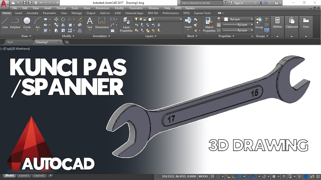
Cara Menggambar Kunci Pas / Spanner di AutoCAD
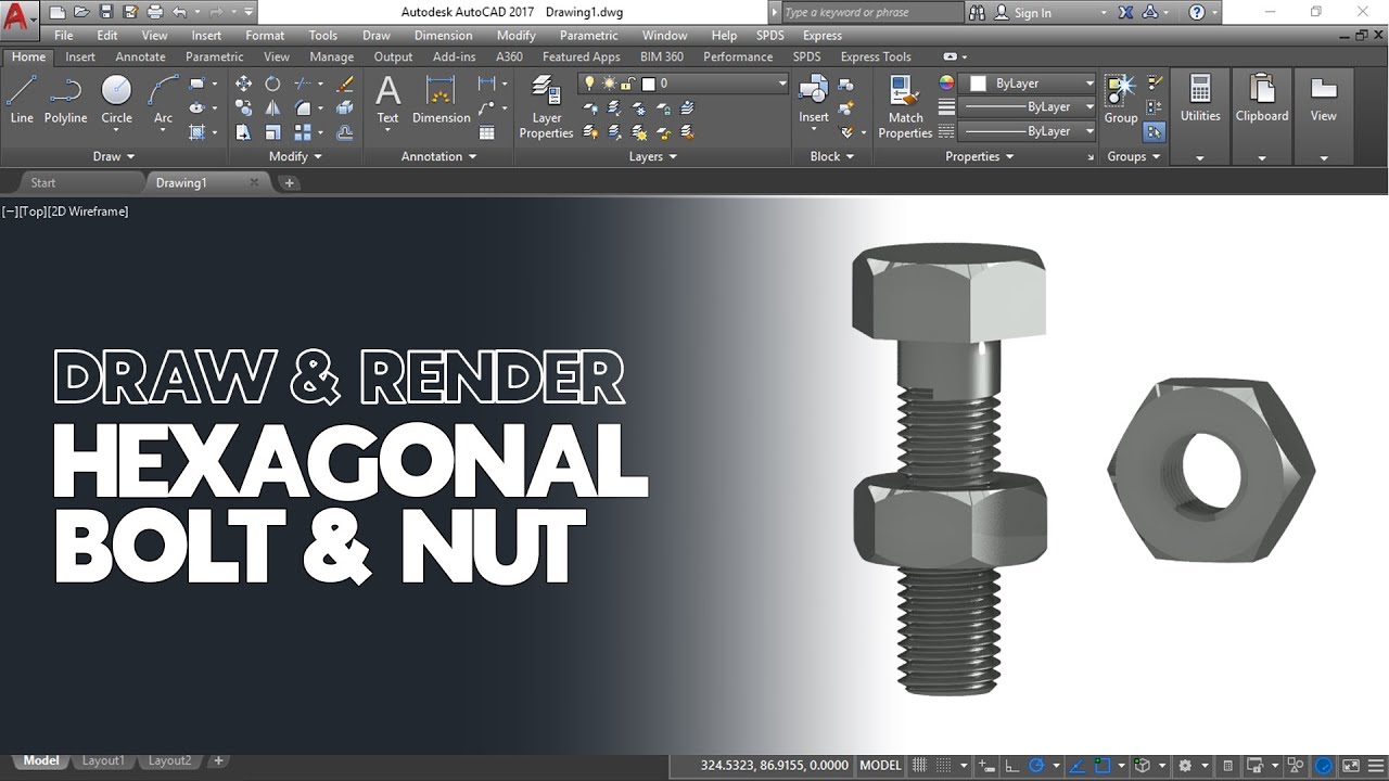
Cara Gambar dan Render Hexagonal Mur dan Baut di AutoCAD
Autocad 2dimensional to 3dimensional beginner # 42 mechanical engineering
Cara menggambar 2d dengan autocad (teknik mesin) #1

Cone axis is inclined to H.P. - Projection of Solids
autocad tutorials for beginners
5.0 / 5 (0 votes)
