Cara Menggambar Kunci Pas / Spanner di AutoCAD
Summary
TLDRIn this detailed tutorial, the instructor demonstrates how to draw a spanner (adjustable wrench) in AutoCAD, focusing on sizes 17 and 15. Starting with workspace settings, the guide covers essential commands such as Line, Ellipse, Offset, Fillet, and more. It provides step-by-step instructions on creating various elements of the spanner, from the head to the handle, and finishing with extrusion and text placement. The tutorial also offers useful tips for adjusting dimensions and using advanced tools like 3D modeling and trimming. Whether you're a beginner or intermediate AutoCAD user, this tutorial offers a thorough and accessible approach.
Takeaways
- 😀 The tutorial covers how to draw a wrench (kunci pas) using AutoCAD, focusing on creating two sizes: 17 and 15.
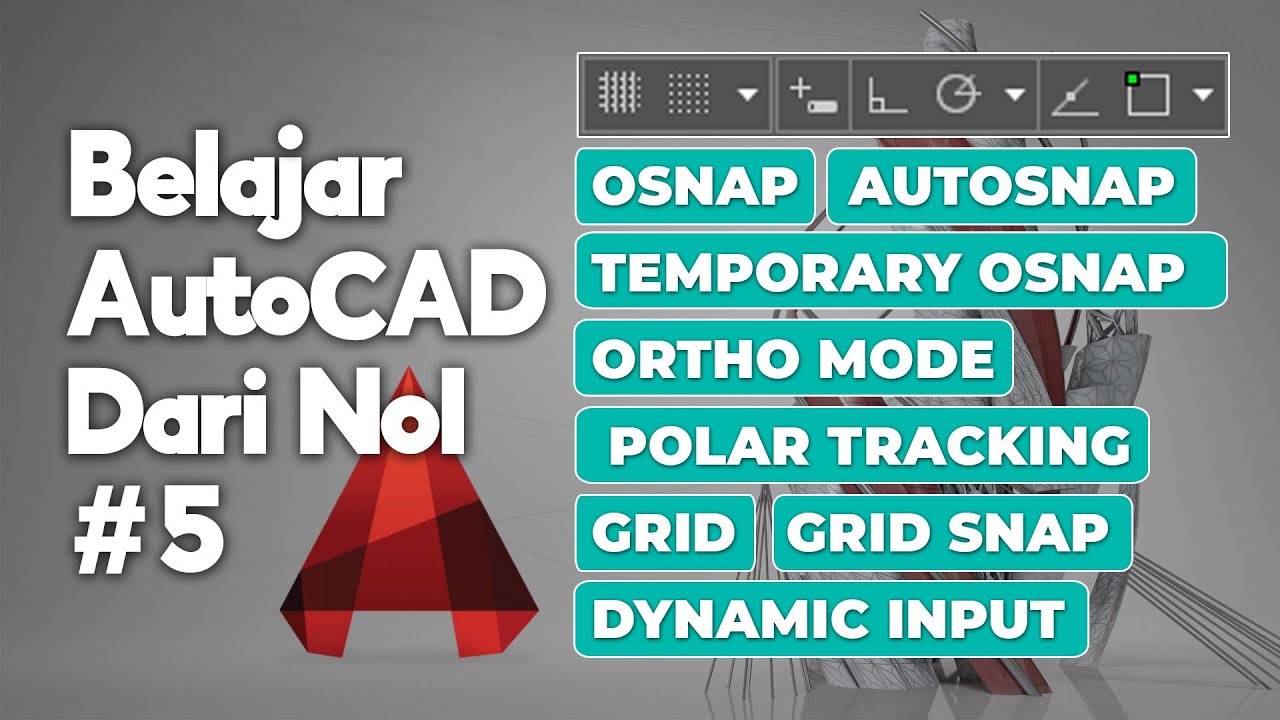
- 😀 The instructor uses AutoCAD's 3D modeling workspace and activates essential tools like 3D osnap, OST, and autosnap.
- 😀 To start, the user draws guiding lines with specific measurements, such as a 17° angle and a 20mm length using the 'Line' command.
- 😀 The wrench head is drawn using an ellipse, which is not a perfect circle but slightly elongated, with dimensions 17 and 15.
- 😀 The instructor demonstrates using the 'Trim' and 'Offset' commands to cut off unnecessary lines and adjust the wrench's head size.
- 😀 Fillet commands are employed to smooth the corners of the wrench, with adjustable radii for different parts of the drawing.
- 😀 Copy, rotate, and scale commands are used to replicate and adjust the wrench parts, ensuring they are in the correct proportions.
- 😀 To check accuracy, the dimensions before and after scaling are compared to ensure proper reduction from 17mm to 15mm.
- 😀 Additional filleting is done on the smaller elements to maintain smooth connections without cutting lines that shouldn't be cut.
- 😀 Text labels with the dimensions '17' and '15' are added to the design, converted into polylines, and then positioned correctly on the 3D model.
- 😀 The final 3D model of the wrench is extruded, and further adjustments are made to ensure everything is centered and aligned properly.
Q & A
What software is being used in the tutorial to create the wrench drawing?
-The software used in the tutorial is AutoCAD, specifically the 3D modeling workspace.
What are the two wrench sizes mentioned in the tutorial?
-The two wrench sizes mentioned are 17mm and 15mm.
What type of workspace view is suggested for this project in AutoCAD?
-The suggested workspace view is the '3D Modeling' workspace.
What AutoCAD tools are recommended to be activated for efficient drawing?
-The recommended tools to activate are 3D OSnap, OST (Object Snap Tracking), and Autosnap 3Tool.
What is the purpose of using the 'Ortho Mode' in AutoCAD during this tutorial?
-'Ortho Mode' is used to ensure that lines are drawn strictly along horizontal or vertical directions, making it easier to create precise straight lines.
How do you draw the head of the wrench using AutoCAD?
-The head of the wrench is drawn using the 'Ellipse' command, which is appropriate because the wrench head is not perfectly circular but slightly elongated.
What is the purpose of the 'Offset' command in this tutorial?
-The 'Offset' command is used to create parallel lines at a specified distance, which is helpful when creating the body and head of the wrench.
How does the tutorial ensure that the 3D extrusions are aligned correctly?
-To ensure proper alignment of the 3D extrusions, the tutorial uses the 'Move' command and adjusts the Z-axis positioning by 1mm to center the extrusions.
What is the reason for using the 'Fillet' command in the design process?
-The 'Fillet' command is used to round off sharp corners, making the design of the wrench smoother and more accurate.
What are the steps to add text and labels for the wrench sizes in the AutoCAD drawing?
-Text is added using the 'Text' tool. The font is set to Arial Rounded, and the text size is adjusted to 4.4. The numbers 17 and 15 are then placed next to the respective parts of the wrench, and the text is exploded to convert it into lines.
Outlines

This section is available to paid users only. Please upgrade to access this part.
Upgrade NowMindmap

This section is available to paid users only. Please upgrade to access this part.
Upgrade NowKeywords

This section is available to paid users only. Please upgrade to access this part.
Upgrade NowHighlights

This section is available to paid users only. Please upgrade to access this part.
Upgrade NowTranscripts

This section is available to paid users only. Please upgrade to access this part.
Upgrade NowBrowse More Related Video
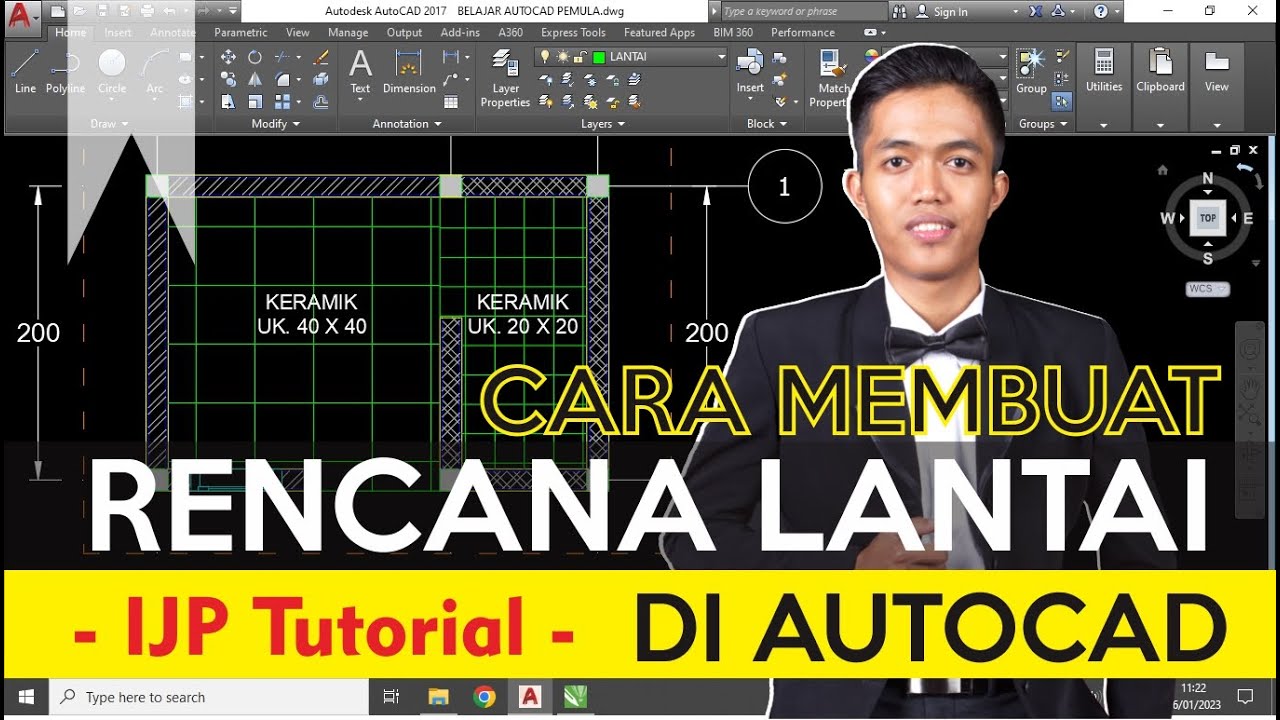
CARA MEMBUAT RENCANA LANTAI DI AUTOCAD
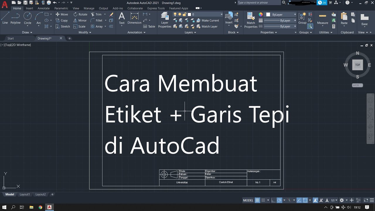
Cara Membuat Garis Tepi dan Etiket Gambar Teknik Kertas A4 di Autodesk AutoCad
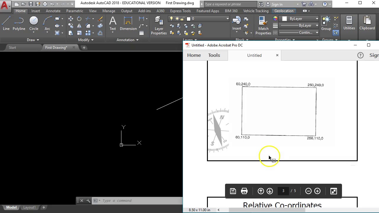
Getting Started with AutoCAD #2 "Lines using absolute and relative co-ordinates"

Cone axis is inclined to H.P. - Projection of Solids
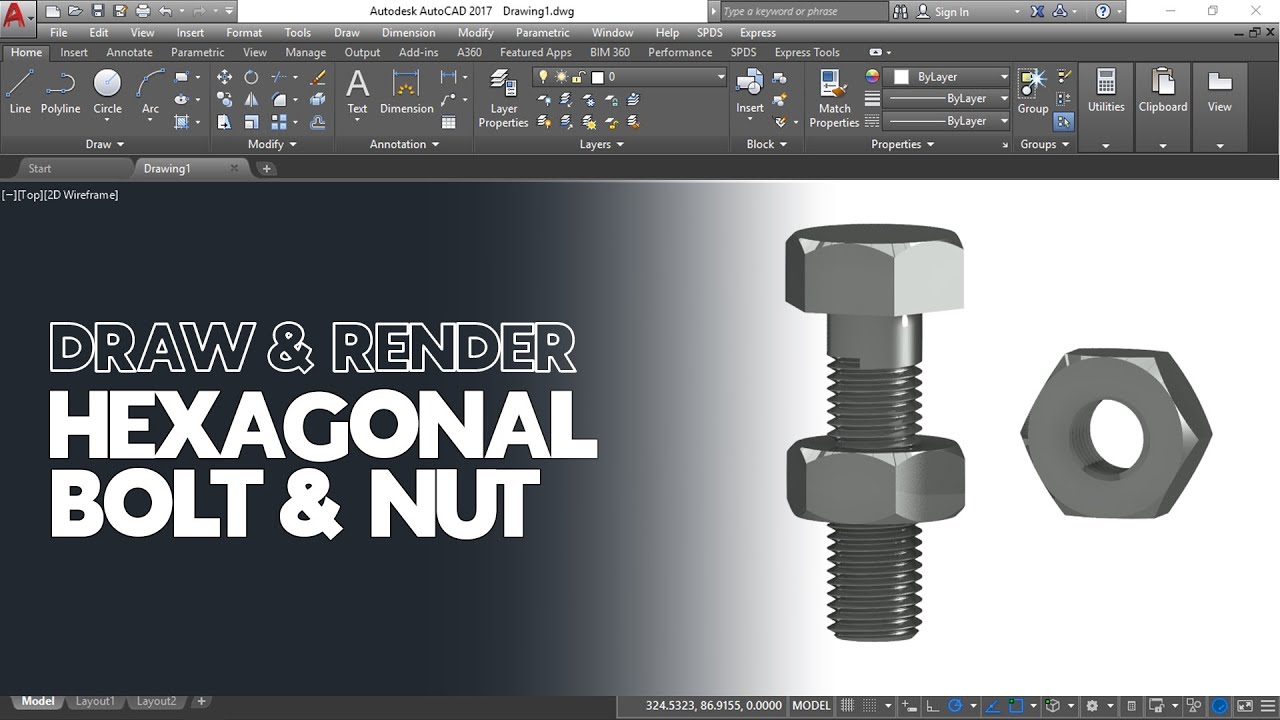
Cara Gambar dan Render Hexagonal Mur dan Baut di AutoCAD
Fungsi ORTHO, OSNAP, AUTOSNAP, TEMPORARY OSNAP, POLAR TRACKING, GRID | Belajar AutoCAD dari Nol #5
5.0 / 5 (0 votes)