QUAD Beams - Are they better than Yagis? Are thicker 'wires' better?
Summary
TLDRJustin G0KSC from Innova Antennas discusses his Quad Yagi Antenna (LFAQ) design, inspired by Yu7XL's work. The LFAQ features adjustable elements for precision and a twin boom design for rigidity and high power handling. Justin covers the antenna's design parameters, benefits like high gain and broadbanding, and its comparison to traditional Yagi antennas. He also addresses the limitations of NEC-based modeling for curved elements and the practicality of the LFAQ for various power levels and frequencies.
Takeaways
- 🌐 Justin G0KSC is the creator of Innova Antennas and shares his designs on his website g0ksc.co.uk.
- 📚 His work is featured in the ARRL Antenna Book and in the DUBUS magazine.
- 📅 In 2021, he covered quad Yagis in DUBUS magazine, which is part of the discussion in the video.
- ⏰ The video might be split into two parts due to YouTube's time limit for videos from channels with fewer than a thousand subscribers.
- 🎯 The main topic is the design and inspiration behind Justin's quad or LF Quad (LFAQ) antenna.
- 🔍 The inspiration for the LFAQ came from YU7XL's antenna designs, particularly the use of solid rods clamped onto a boom.
- 🛠️ Justin wanted to make the quad elements adjustable to fine-tune the antenna's performance.
- 📡 The LFAQ features twin booms, which allow for easy adjustment and better performance stability.
- 🔩 The antenna design includes a break at the bottom of the driven element for feeding and an insulator for the coaxial cable.
- 🔗 The LFAQ is designed to be simple to maintain and can handle high power levels, making it suitable for various conditions.
- 📊 The video discusses the trade-offs between the number of elements in a Yagi or Quad antenna and their performance, including gain and bandwidth.
- 📈 Justin uses a slide to illustrate the effective gain per foot of boom and how it compares between Yagi and Quad antennas with similar bandwidths.
Q & A
Who is Justin G0KSC and what is his association with Innova Antennas?
-Justin G0KSC is associated with Innova Antennas and also operates the website g0ksc.co.uk where he publishes his antenna designs.
Where can one find Justin G0KSC's work published?
-Justin G0KSC's work can be found in the ARRL Antenna Book, D-STAR magazine, and his website g0ksc.co.uk.
What is the subject of the first part of Justin's discussion in the video?
-The first part of the discussion focuses on Quad Yagis and their design aspects.
What is the potential limitation of YouTube's video length for Justin's channel?
-YouTube limits the video length for channels with less than a thousand subscribers to around 15 minutes.
What is the inspiration behind Justin's LF Quad antenna design?
-The inspiration for Justin's LF Quad antenna design comes from Yu7XL's website, specifically the use of tubes or solid rods clamped onto a boom.
What is the main issue Justin has with the curved elements of the antenna design he mentions?
-The main issue is that curved elements reduce the accuracy of NEC-based antenna modeling, which could result in the antenna not performing as expected.
What is the purpose of making the tip lamps of the antenna adjustable?
-Making the tip lamps adjustable allows for fine-tuning the size of the elements to position the antenna exactly where needed.
What is the benefit of having twin booms in Justin's LF Quad antenna design?
-Twin booms allow for a single through-the-boom U-bolt on each side, providing stability and making the antenna easier to assemble and adjust.
How does the design of the LF Quad antenna help with static build-up and protecting the transceiver?
-The design includes an insulator running through the boom, which helps to remove static build-up and protect the transceiver by preventing electrical discharge.
What is the advantage of using larger diameter elements in a Quad antenna?
-Larger diameter elements can achieve higher gain and help to broadband the antenna, making it more efficient and stable.
Why did Clarence Moore W9LZX develop the Quad antenna?
-Clarence Moore W9LZX developed the Quad antenna to help remove higher altitude issues and prevent coronal discharge from melting the element tips of Yagi antennas.
What is the trade-off Justin considers when deciding the number of elements for a Quad antenna?
-Justin considers the balance between performance and the additional hardware, weight, and complexity. He finds that beyond seven elements, the performance benefit does not warrant the increase in these factors.
Outlines

このセクションは有料ユーザー限定です。 アクセスするには、アップグレードをお願いします。
今すぐアップグレードMindmap

このセクションは有料ユーザー限定です。 アクセスするには、アップグレードをお願いします。
今すぐアップグレードKeywords

このセクションは有料ユーザー限定です。 アクセスするには、アップグレードをお願いします。
今すぐアップグレードHighlights

このセクションは有料ユーザー限定です。 アクセスするには、アップグレードをお願いします。
今すぐアップグレードTranscripts

このセクションは有料ユーザー限定です。 アクセスするには、アップグレードをお願いします。
今すぐアップグレード関連動画をさらに表示

BAGAIMANA CARA KERJA ANTENA?

Radiation Patterns of Antenna (Isotropic Antenna, Directional Antenna & Omnidirectional Antenna)
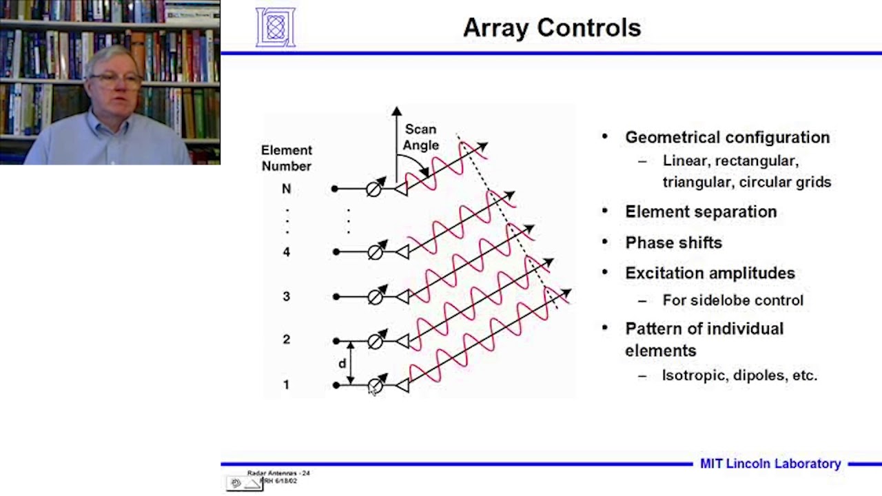
Introduction to Radar Systems – Lecture 6 – Radar Antennas; Part 3
ATPL Radio Navigation - Class 2: Antennas.

Best WiFi Antennas | Parabolic, MIMO, and More!

How does an Antenna work? | ICT #4
5.0 / 5 (0 votes)
