Tutorial Topologi Jaringan Sederhana menggunaan Cisco Packet Tracer (Topologi Tree)
Summary
TLDRIn this tutorial, Rizki Ayu and Safitri Nasution from Politeknik Negeri Jember demonstrate how to create a simple network topology using Cisco Packet Tracer. The process involves setting up a server, three switches, and four PCs, configuring IP addresses, and testing the network with ping and message sending. The tutorial walks through each step, including configuring default gateways and ensuring successful communication between devices. A visual simulation of the network traffic highlights the message flow, offering a clear guide for beginners to understand basic networking principles.
Takeaways
- 😀 The tutorial introduces the network topology as a 'Triangular' layout using Cisco Packet Tracer.
- 😀 The goal is to create a simple network topology using one server, three switches, and four PCs.
- 😀 The first step is to configure the server's IP address by using 'ipconfig' and setting it to 192.168.1.1.
- 😀 Each PC is assigned an IP address starting from 192.168.1.2, and the default gateway is set to 192.168.1.1.
- 😀 All PCs and the server must have different IP addresses, but share the same default gateway (192.168.1.1).
- 😀 The tutorial demonstrates how to configure IP settings on the server and all PCs individually.
- 😀 The process involves testing the network connection using the 'ping' command to verify that all devices can communicate.
- 😀 A successful ping from any PC to the server confirms that the devices are connected correctly in the network.
- 😀 Additionally, a message can be sent from the server to a PC as another way to test the connection between devices.
- 😀 The tutorial ends by showing how the message travels from the server through the switches to the destination PC, completing the basic setup of the network topology.
Q & A
Who created the tutorial and what program are they from?
-The tutorial was created by Rizki Ayu Safitri Nasution from the Informatics Management Program, Class C, at Politeknik Negeri Jember.
What is the main objective of the tutorial?
-The main objective is to demonstrate how to create a simple triangular network topology using Cisco Packet Tracer.
Which devices are used in the triangular network topology?
-The topology uses 1 server, 3 switches, and 4 PCs.
How are all the devices connected in this network topology?
-All devices are connected using cables, forming a triangular structure among the switches.
What IP address is assigned to the server?
-The server is assigned the IP address 192.168.1.1.
How are the IP addresses and default gateway configured on the PCs?
-Each PC is assigned a unique IP address in the 192.168.1.x range, while the default gateway for all PCs is set to 192.168.1.1.
Why is it important to differentiate each PC's IP address?
-Differentiating each PC's IP address ensures unique identification on the network, preventing IP conflicts and enabling proper communication between devices.
How can connectivity be tested between devices in this topology?
-Connectivity can be tested using the ping command in the Command Prompt of any PC or the server, targeting other devices' IP addresses.
What additional testing method is used to verify communication between the server and PCs?
-The tutorial also uses the 'Send Message' feature in Packet Tracer to send messages from the server to the last PC, visually confirming successful communication.
What does the simulation in Packet Tracer show when sending a message?
-The simulation shows the path of the message traveling from the server to Switch 0, then to the second switch, and finally to the target PC, illustrating the flow of data through the network.
Outlines

Cette section est réservée aux utilisateurs payants. Améliorez votre compte pour accéder à cette section.
Améliorer maintenantMindmap

Cette section est réservée aux utilisateurs payants. Améliorez votre compte pour accéder à cette section.
Améliorer maintenantKeywords

Cette section est réservée aux utilisateurs payants. Améliorez votre compte pour accéder à cette section.
Améliorer maintenantHighlights

Cette section est réservée aux utilisateurs payants. Améliorez votre compte pour accéder à cette section.
Améliorer maintenantTranscripts

Cette section est réservée aux utilisateurs payants. Améliorez votre compte pour accéder à cette section.
Améliorer maintenantVoir Plus de Vidéos Connexes

Membuat Topologi Jaringan 1 Gedung 3 Lantai Menggunakan Cisco Paket Tracer
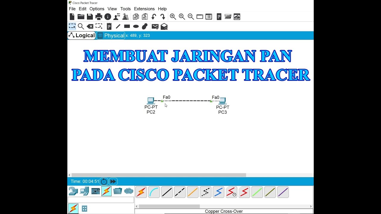
Membuat Jaringan PAN pada Cisco Packet Tracer

Basics of Cisco Packet Tracer (Part 2) | Hub
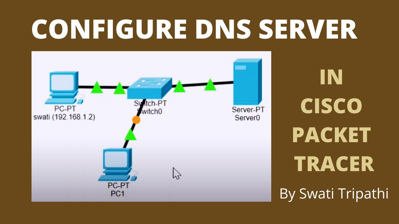
DNS Server Configuration in Cisco Packet Tracer

Jaringan Komputer Sederhana | Tutorial Belajar Online Lengkap CISCO CCNA 200-301 Part 5

Netzwerktutorial: Cisco Packet Tracer - Installation, Konfiguration & ein erster Aufbau
5.0 / 5 (0 votes)
