Fusion 360 beginner's Exercise #6 - Fusion 360 tutorial | Spark Plug |
Summary
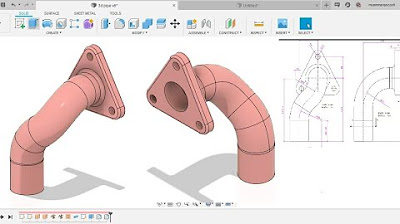
TLDRIn this tutorial video, the host guides viewers through the process of creating a complex 3D component using a CAD software. Starting from the front view, the tutorial covers sketching, extruding, and mirroring to form the component's shape. Special attention is given to the correct dimensions and radii, ensuring the design's accuracy. The video also demonstrates how to handle the top view and provides tips for avoiding unnecessary edges. By the end, viewers are shown a completed component with a polished appearance, ready for further use or modification.
Takeaways
- 📚 The video is a tutorial focused on creating a specific component by referring to its drawing.
- 🔍 The tutorial is the sixth in a series and a downloadable file can be found in the video description.
- 📐 The component design includes a front view, top view, and isometric view for full understanding.
- 🛠️ The process starts with creating the front view on the front plane, followed by extrusion to form the component's shape.
- 🔲 The tutorial explains how to handle the absence of certain dimensions like the radius, by calculating them based on given distances.
- ⭕ It demonstrates the use of construction lines, circles, and tangent constraints to form the front view profile.
- 🔄 The video guides through mirroring and trimming lines to complete the front view sketch.
- 📏 Dimensions and distances are carefully measured and applied to ensure accuracy in the design.
- 🔑 The extrusion process is explained with specific attention to the component's thickness and symmetry.
- 🔼 The top view is created on an offset plane to avoid intersection with the solid body, emphasizing the importance of proper plane selection.
- 🔧 The final steps involve adding the necessary radii to the design and providing a final appearance to the component.
Q & A
What is the main topic of the video tutorial?
-The main topic of the video tutorial is to demonstrate how to create a specific component by interpreting its drawing.
What is the purpose of the isometric view in the tutorial?
-The isometric view serves to provide a comprehensive understanding of the component's shape after the drawing is fully completed.
What is the first step in creating the component in the tutorial?
-The first step is to make the front view on the front plane and then attach it to the front view on the front plane.
How many circles are involved in the front view sketch, and what are their radii?
-There are two circles in the front view sketch with outer radii of 24mm and 50mm, and inner radii of 12mm and 36mm, respectively.
Why are the tangent lines created in the tutorial?
-The tangent lines are created to join the circles in the front view sketch, ensuring a smooth transition between the shapes.
What is the significance of the construction line in the tutorial?
-The construction line is used as a reference for creating symmetry and for mirroring elements in the sketch.
How is the inner profile of the component created in the tutorial?
-The inner profile is created by finding the radius of the inner circle based on given distances and then drawing and trimming arcs and lines accordingly.
What is the extrusion distance for the component, and how is it determined?
-The extrusion distance is 60mm, determined by the maximum thickness of the component from the front and top views, with 30mm extruded symmetrically from each side.
Why is the top plane offset in the tutorial?
-The top plane is offset to avoid intersection with the solid body, allowing the selection of lines for the top profile sketch.
How are the radii provided in the final stages of the tutorial?
-The radii are provided manually at the end of the 3D modeling process using the fillet command, ensuring smooth edges where necessary.
What does the tutorial suggest for the appearance of the final component?
-The tutorial suggests using the 'a' command to apply an appearance to the final component, such as a metallic look.
Outlines

Cette section est réservée aux utilisateurs payants. Améliorez votre compte pour accéder à cette section.
Améliorer maintenantMindmap

Cette section est réservée aux utilisateurs payants. Améliorez votre compte pour accéder à cette section.
Améliorer maintenantKeywords

Cette section est réservée aux utilisateurs payants. Améliorez votre compte pour accéder à cette section.
Améliorer maintenantHighlights

Cette section est réservée aux utilisateurs payants. Améliorez votre compte pour accéder à cette section.
Améliorer maintenantTranscripts

Cette section est réservée aux utilisateurs payants. Améliorez votre compte pour accéder à cette section.
Améliorer maintenantVoir Plus de Vidéos Connexes
Fusion 360 beginner's Exercise #8 - Fusion 360 tutorial
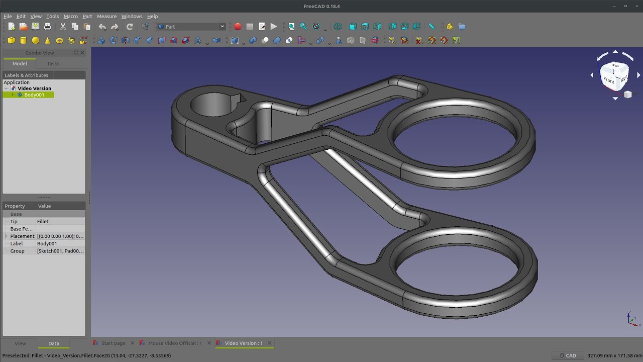
FreeCAD Practice Part |JOKO ENGINEERING|
SolidWorks - Tutorial for Beginners in 13 MINUTES! [ COMPLETE ]

Computer Mouse Surface Modelling in Creo 3.0 | Creo Beginner Tutorial 2021

How to make 2D Nuts into 3D in AutoCAD
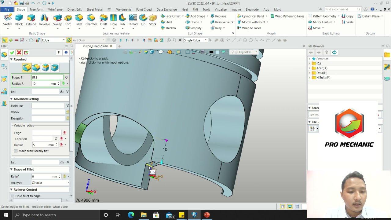
Tutorial Piston Head 3D - ZW3D
5.0 / 5 (0 votes)
