AC Through Series RL Circuit - AC Circuits - Basic Electrical Engineering
Summary
TLDRThis video delves into the behavior of alternating current (AC) in a series circuit with a resistor and an inductor. It explores key concepts such as voltage, current, impedance, and power factor, highlighting how voltage leads current in inductive circuits. The presenter explains the voltage and impedance triangles, detailing how to calculate real, reactive, and apparent power using the relationships between these parameters. By illustrating the phase relationships and power factor, viewers gain insights into the effective use of AC circuits, making it essential for understanding electrical engineering principles.
Takeaways
- 😀 AC voltage applied to a series connection of an inductor and resistor affects the current's nature, power, and power factor.
- 🔌 In a series circuit, the same current flows through both the resistor and inductor, causing two distinct voltage drops.
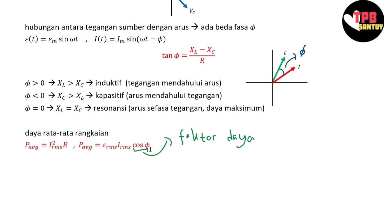
- 📊 Voltage across a resistor is in phase with the current, while voltage across an inductor leads the current by 90 degrees.
- 📐 The voltage triangle illustrates the relationship between the applied voltage, voltage across the resistor, and voltage across the inductor using Pythagorean theorem.
- 🔍 Impedance (Z) represents the total opposition to AC current flow and is expressed as a combination of resistance (R) and inductive reactance (X_L).
- 📏 The impedance can be expressed in rectangular form as Z = R + jX_L, indicating its complex nature.
- ⚡ Instantaneous power is calculated by multiplying the voltage and current, yielding oscillatory terms that represent power variations over time.
- 🔺 The power triangle relates real power (P), reactive power (Q), and apparent power (S), illustrating their interconnections.
- ⚖️ Power factor (PF) is the ratio of real power to apparent power, indicating how effectively electrical power is converted into useful work.
- 📉 In inductive circuits, the current lags the voltage, resulting in a lagging power factor, which influences the overall power consumption.
Q & A
What is the primary focus of the video?
-The video explains the behavior of AC voltage in a series circuit containing a resistor and an inductor, discussing parameters such as current, power, and power factor.
How is the applied voltage represented in the circuit?
-The applied voltage is represented as V(t) = V_M sin(ωt), where V_M is the maximum voltage and ω is the angular frequency.
What are the voltage drops across the resistor and inductor in the circuit?
-The voltage drop across the resistor (V_R) is given by Ohm's law as I * R, and the voltage drop across the inductor (V_L) is I * X_L, where X_L is the inductive reactance.
What does the phase relationship between voltage and current indicate in a pure inductor?
-In a pure inductor, the voltage leads the current by 90 degrees, meaning the current lags the voltage.
What is the significance of Kirchhoff's voltage law in the circuit analysis?
-Kirchhoff's voltage law states that the sum of the voltages around a closed loop in a circuit must equal zero, which helps determine the supply voltage in relation to voltage drops across circuit elements.
What is the impedance in an RL circuit, and how is it represented?
-Impedance (Z) in an RL circuit is defined as the opposition to AC current flow and is represented as Z = R + jX_L, where R is resistance and X_L is inductive reactance.
What is the formula for calculating average power in an inductive circuit?
-The average power (P) in an inductive circuit is given by P = V_RMS * I_RMS * cos(ϕ), where ϕ is the phase angle between the voltage and current.
Can you explain the difference between active power (P), reactive power (Q), and apparent power (S)?
-Active power (P) is the actual power consumed by the load, reactive power (Q) is associated with the energy storage in the circuit, and apparent power (S) is the combination of both, calculated as S = P + jQ.
What determines the power factor in a circuit?
-The power factor is determined by the phase angle (ϕ) between the voltage and current. It is defined as the ratio of active power to apparent power, given by cos(ϕ).
How does the nature of current in an inductive circuit affect the power factor?
-In an inductive circuit, the current lags the voltage, leading to a lagging power factor, which is expressed as cos(ϕ) where ϕ is positive due to the phase difference.
Outlines

Cette section est réservée aux utilisateurs payants. Améliorez votre compte pour accéder à cette section.
Améliorer maintenantMindmap

Cette section est réservée aux utilisateurs payants. Améliorez votre compte pour accéder à cette section.
Améliorer maintenantKeywords

Cette section est réservée aux utilisateurs payants. Améliorez votre compte pour accéder à cette section.
Améliorer maintenantHighlights

Cette section est réservée aux utilisateurs payants. Améliorez votre compte pour accéder à cette section.
Améliorer maintenantTranscripts

Cette section est réservée aux utilisateurs payants. Améliorez votre compte pour accéder à cette section.
Améliorer maintenantVoir Plus de Vidéos Connexes

AC Through Series RC Circuit - AC Circuits - Basic Electrical Engineering
Rangkaian Seri RLC | Rangkaian AC | Part 2 | Fisika Dasar
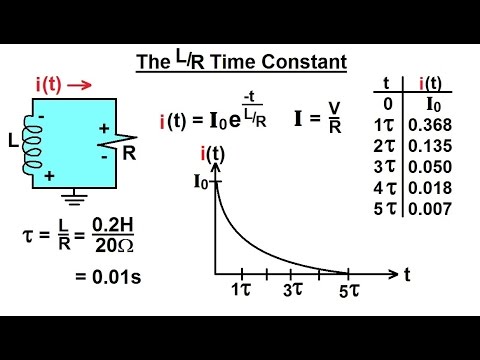
Electrical Engineering: Ch 8: RC & RL Circuits (11 of 43) The L/R Time Constant
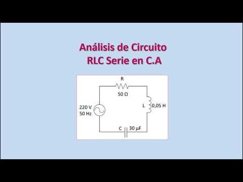
Análisis de Circuitos RLC en Corriente Alterna. Diagrama Fasorial. Ejercicio Resuelto.

Three Phase AC Circuits : Problem 1 - Three Phase Circuits - Basic Electrical Engineering
The Ultimate Guide to Understanding Inductance and Inductors
5.0 / 5 (0 votes)
