How to Use a Breadboard
Summary
TLDRThis video by Ben Finio from Science Buddies offers a comprehensive guide to using a breadboard for electronic circuits. It explains the breadboard's structure, how to insert components, and the importance of correct connections. The tutorial covers common mistakes, the use of jumper wires, and integrating circuits, providing a solid foundation for beginners in electronics.
Takeaways
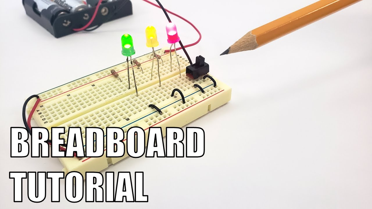
- 🔌 A breadboard is a rectangular plastic with a grid of holes designed for building electronic circuits without soldering.
- 💡 Breadboards are used for creating simple to complex circuits, including those with automatic flashing lights and various robots.
- 📚 The term 'breadboard' originates from early electronic circuits that used wooden boards with nails or screws for connections.
- 📏 Breadboards come in different sizes like full-size, half-size, and mini, with options to snap multiple boards together for larger projects.
- 🔩 The holes in a breadboard are designed to hold the leads of electronic components, providing a secure yet easily adjustable connection.
- 🛠 When flipped, breadboards reveal metal strips that make the electrical connections to the inserted components.
- 📏 Breadboards are labeled with columns from A to J and rows numbered, aiding in following circuit-building instructions.
- 🔋 The power buses on the sides of the breadboard, usually red and black, are used to distribute power to the circuit, with the red typically connected to the positive terminal.
- 🔄 Understanding the internal connections of the breadboard is crucial for proper circuit assembly, with sets of five holes being electrically connected.
- 🚫 Common mistakes include incorrect wiring, loose connections, and incorrect orientation of components with polarity, like LEDs.
- 🛠️ Choosing the right type of jumper wires is important for circuit organization, with options ranging from flexible wires to pre-cut kits to homemade wires from hookup wire.
- 💡 The central gap in a breadboard is designed to accommodate dual in-line package integrated circuits, ensuring their pins are correctly aligned with the electrical connections.
Q & A
What is a breadboard and what is its primary function?
-A breadboard is a rectangular piece of plastic with a grid of holes that allows for the easy and quick assembly of electronic circuits by inserting electronic components into these holes. Its primary function is to facilitate the building of simple to complex electronic circuits without the need for soldering.
Can you explain the origin of the term 'breadboard'?
-The term 'breadboard' originates from the early days of electronic circuits when wooden boards with screws or nails were used to make electronic connections, resembling a kitchen breadboard.
What are the common sizes of breadboards mentioned in the script?
-The common sizes of breadboards mentioned are full-size, half-size, and mini breadboards.
How do breadboards hold electronic components in place without soldering?
-Breadboards hold electronic components in place using metal clips inside the board that grab onto the leads of the components when they are pushed into the holes. This is why they are called solderless breadboards.
What is the purpose of the adhesive backing on a breadboard?
-The adhesive backing on a breadboard allows it to be permanently stuck onto a project, providing a stable base for the electronic components.
How are the holes on a breadboard electrically connected?
-Each set of five holes in a row (A through E and F through J) is electrically connected. Additionally, the power buses on the sides of the breadboard provide a complete path for electricity to flow through the circuit.
What is the significance of the gap in the middle of the breadboard?
-The gap in the middle of the breadboard is designed to accommodate integrated circuits in a dual in-line package, allowing the pins on each side of the chip to be connected to their own row, preventing short circuits.
What are some common mistakes made by beginners when using a breadboard?
-Common mistakes include not placing components in the correct row to maintain electrical connection, not pushing leads or wires firmly into the breadboard, and not considering the polarity of components like LEDs.
Why is it important to check the polarity of components like LEDs?
-Checking the polarity of components like LEDs is important because the direction they are facing matters for the circuit to function correctly. The longer leg of an LED is positive and must be connected to the positive side of the power source.
What are the different types of jumper wires mentioned in the script and their advantages and disadvantages?
-The script mentions three types of jumper wires: long flexible wires that can become messy, pre-cut wires in a kit that are neater but limit length options, and hookup wire that can be cut and stripped to length for customized use but requires additional tools.
What type of wire should be used for making jumper wires and why?
-Solid-core wire should be used for making jumper wires because it is stiff and easy to push into a breadboard. Stranded wire, while more flexible overall, has ends that are also flexible and harder to insert without bending.
Outlines

Esta sección está disponible solo para usuarios con suscripción. Por favor, mejora tu plan para acceder a esta parte.
Mejorar ahoraMindmap

Esta sección está disponible solo para usuarios con suscripción. Por favor, mejora tu plan para acceder a esta parte.
Mejorar ahoraKeywords

Esta sección está disponible solo para usuarios con suscripción. Por favor, mejora tu plan para acceder a esta parte.
Mejorar ahoraHighlights

Esta sección está disponible solo para usuarios con suscripción. Por favor, mejora tu plan para acceder a esta parte.
Mejorar ahoraTranscripts

Esta sección está disponible solo para usuarios con suscripción. Por favor, mejora tu plan para acceder a esta parte.
Mejorar ahoraVer Más Videos Relacionados
Breadboard Tutorial

Complete beginner's guide to using a breadboard

How to Make a Simple Refracting Telescope (Monocular) | STEM Activity

All electronic components names, functions, testing, pictures and symbols - smd components
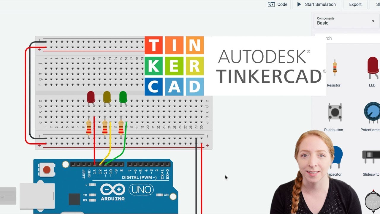
LEDs & Breadboards With Arduino in Tinkercad

Chapitre 2: Quadripôle passif -partie 1-résumé du cours
5.0 / 5 (0 votes)
