Turning operation in CREO manufacturing with generating NC part programme
Summary
TLDRThis video demonstrates the process of generating a CNC part program using Creo 7.0. It covers modeling a part, creating CNC programs, and executing them on a CNC machine. The tutorial includes step-by-step guidance on setting up work directories, creating parts, and applying turning operations like rough and profile turning. The video also covers the creation of raw materials, coordinate systems, and machine simulation for the CNC program, concluding with saving and generating the final CNC program for area and profile turning operations.
Takeaways
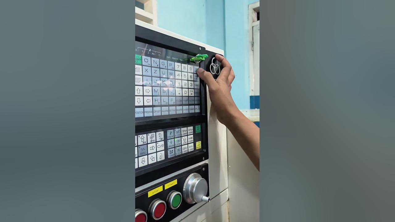
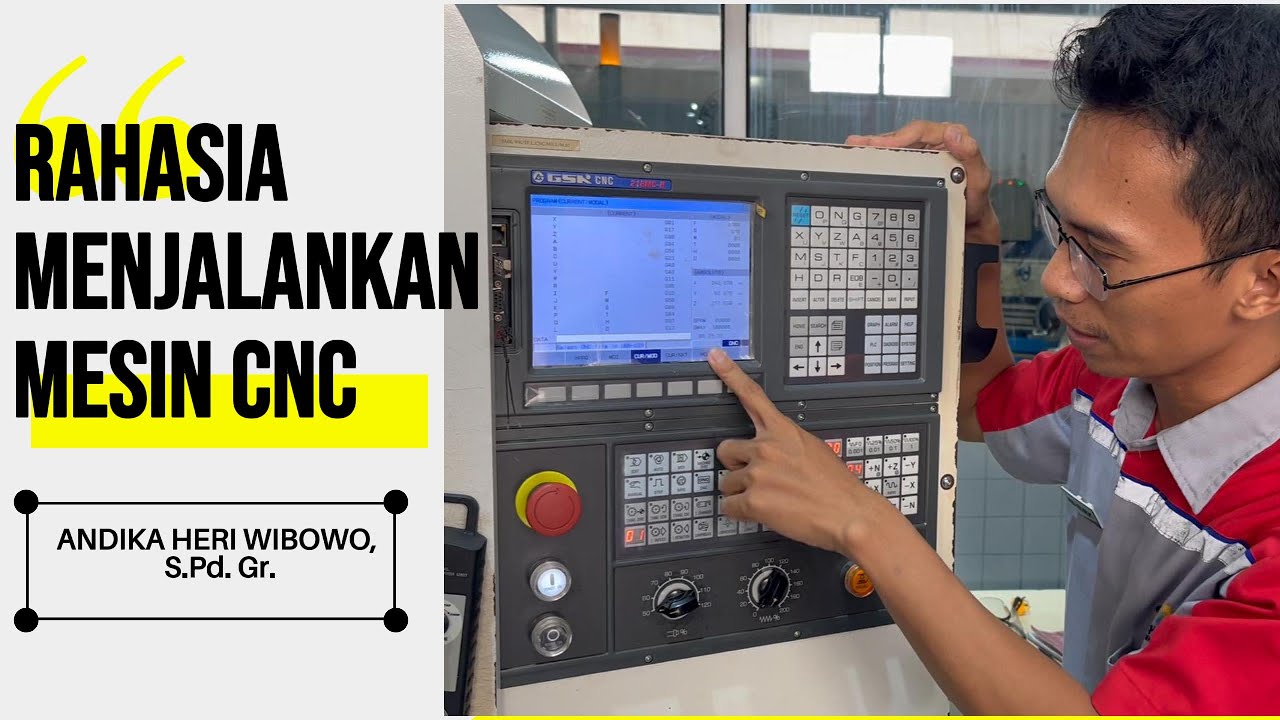
- 😀 The script demonstrates how to generate a CNC part program using Creo 7.0 and execute it on a CNC machine.
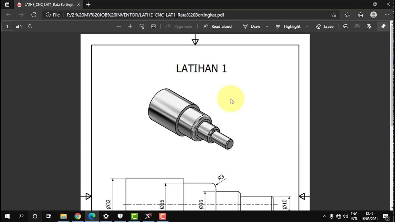
- 😀 The process starts with creating a 3D model of a part, which includes specific dimensions (80 mm, 60 mm, and 40 mm diameters with a 30 mm length).
- 😀 Work directories are created to store models, and the appropriate template is selected for part modeling in Creo.
- 😀 The sketching process includes defining the dimensions of the model, ensuring the lines and shapes meet the necessary measurements.
- 😀 The model is then revolved around an axis to create a 3D part shape, and chamfering is applied to some edges for finishing.
- 😀 After modeling, the CNC program is created using Creo's manufacturing options and selecting the appropriate NC assembly.
- 😀 A coordinate system is created to define the position of the workpiece on the machine, ensuring proper alignment.
- 😀 A raw material (workpiece) is defined with either a rectangular or circular cross-section, and a reference model is selected for the CNC program.
- 😀 Operations are set based on the machine type, with the turning operation defined to match the workpiece's shape and size.
- 😀 The area turning operation is selected for rough turning, and profile turning is selected for finishing the part. Tool paths are checked for accuracy.
- 😀 The final CNC program is generated in the form of a CL file, and the program is simulated to ensure proper material removal before execution.
Q & A
What software is being used to generate the CNC part program in this tutorial?
-The software used is Creo 7.0, which is a parametric modeling software used to create the part and generate the CNC program.
What is the first step in creating the CNC part program using Creo 7.0?
-The first step is to create the part model, starting by setting up the work directory and selecting the correct template for the part.
How is the model created in Creo 7.0 for CNC programming?
-The model is created by selecting the front plane, sketching the profile using lines, and defining dimensions for features like diameter and length, followed by using the 'Revolve' option to create a 3D part.
What type of operations are performed on the model in the tutorial?
-The operations performed include rough turning and finish turning, specifically area turning and profile turning, to shape the part as per the given design.
What is the significance of the workpiece creation step in the CNC programming process?
-The workpiece creation step involves defining the raw material or stock, which is used to shape the final product. This helps set the reference for the CNC machining operations.
How is the coordinate system set up in Creo for CNC programming?
-The coordinate system is created by selecting a reference plane and aligning the coordinate axes (X, Y, Z) to match the part’s orientation. This helps in setting up the machining operations accurately.
What type of machine is selected for this CNC programming tutorial?
-A lathe machine is selected, which is appropriate for turning operations like rough turning and profile turning.
What is the purpose of using the 'Tool Path' function in the CNC program creation?
-The 'Tool Path' function helps in simulating and visualizing the tool's movement on the part. This ensures the tool correctly follows the desired path during the machining process.
Why is the simulation step important in the CNC programming process?
-Simulation is important because it allows checking the tool’s movements and material removal processes, helping to verify that the part will be machined correctly before actual execution on the CNC machine.
How is the final CNC program generated in Creo 7.0?
-The final CNC program is generated by selecting the post-operation options in Creo, where the program is saved in a CL file format. The NC sequence for different operations (like area turning and profile turning) is then saved and ready for execution.
Outlines

Esta sección está disponible solo para usuarios con suscripción. Por favor, mejora tu plan para acceder a esta parte.
Mejorar ahoraMindmap

Esta sección está disponible solo para usuarios con suscripción. Por favor, mejora tu plan para acceder a esta parte.
Mejorar ahoraKeywords

Esta sección está disponible solo para usuarios con suscripción. Por favor, mejora tu plan para acceder a esta parte.
Mejorar ahoraHighlights

Esta sección está disponible solo para usuarios con suscripción. Por favor, mejora tu plan para acceder a esta parte.
Mejorar ahoraTranscripts

Esta sección está disponible solo para usuarios con suscripción. Por favor, mejora tu plan para acceder a esta parte.
Mejorar ahora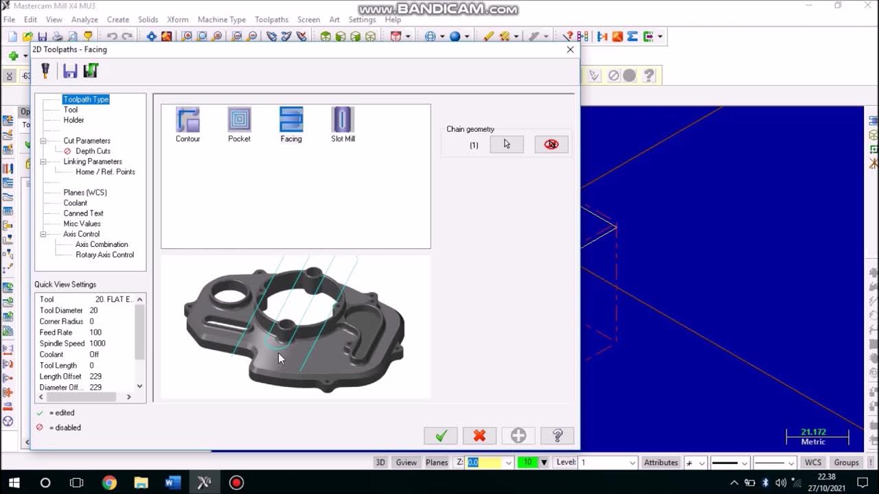


5.0 / 5 (0 votes)
